Self-calibration method for ray collimator and system thereof

A collimator and self-calibration technology, applied in the field of medical imaging, can solve problems such as the complex calibration process of the ray collimator, and achieve the effects of easy debugging and reduced error probability.

Active Publication Date: 2019-03-08
SHENZHEN ANKE HIGH TECH CO LTD
View PDF15 Cites 4 Cited by
  • Summary
  • Abstract
  • Description
  • Claims
  • Application Information

AI Technical Summary

Problems solved by technology

[0005] The technical problem to be solved by the present invention is to provide a self-calibration method and system of a ray collimator for the

Method used


Image

  • Self-calibration method for ray collimator and system thereof
  • Self-calibration method for ray collimator and system thereof
  • Self-calibration method for ray collimator and system thereof

Examples


Embodiment Construction

[0052] In order to make the object, technical solution and advantages of the present invention more clear and definite, the present invention will be further described in detail below with reference to the accompanying drawings and examples. It should be understood that the specific embodiments described here are only used to explain the present invention, not to limit the present invention.

[0053] Please also see Figure 1-Figure 4 , the present invention provides some embodiments of a self-calibration method for a ray collimator.

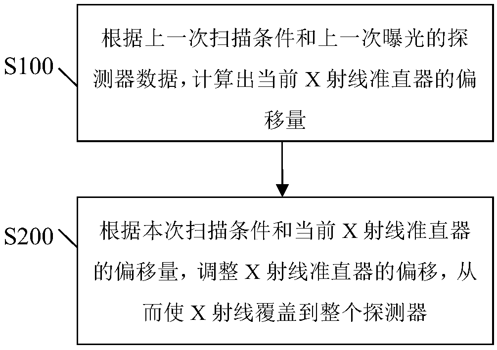
[0054] Such as figure 1 Shown, a kind of self-calibration method of ray collimator comprises the following steps:

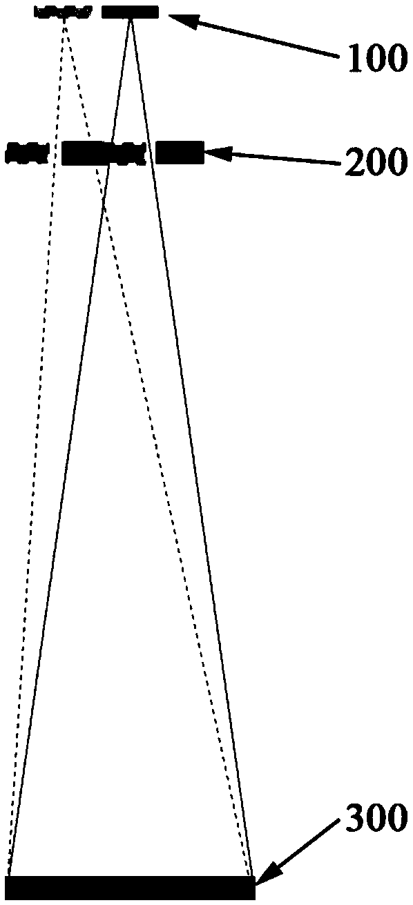
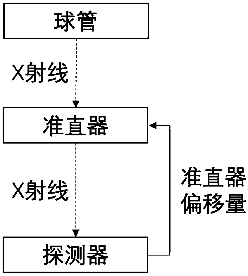
[0055]Step S100 , calculating the current offset of the X-ray collimator 200 according to the last scanning condition and the detector data of the last exposure.

[0056] Specifically, the drift of the tube focus 100 in the z direction is related to a number of scan conditions. These scanning conditions include: exposure volta...


PUM


Abstract

The invention discloses a self-calibration method for a ray collimator and a system thereof. The method comprises the steps of calculating an offset of a current X-ray collimator according to a previous scanning condition and detector data of previous exposure; according to the current scanning condition and the offset of the current X-ray collimator, adjusting the offset of the X-ray collimator,so that X-rays cover an entire detector. Since all calibration methods can be implemented by software of a reconstruction machine, there is no need to increase the hardware cost to ensure communication between the detector and the collimator, and hardware algorithm integration is also not needed. The difficulty of developing the software on the reconstruction machine is easier and simpler than implementing of a dynamic tracking algorithm on the hardware, the system is also easy to debug, and the probability of errors can be greatly reduced.

Description

technical field [0001] The invention relates to the technical field of medical imaging, in particular to a self-calibration method and system of a ray collimator. Background technique [0002] A complete CT imaging system usually includes an X-ray source and a detector array. The beam from the X-ray source is attenuated by the object, reaches the detector and is converted into a digital signal. These digital signals are processed by appropriate correction algorithms, sent to the reconstruction system and finally converted into scanned images. After the X-rays are emitted from the tube, in order to avoid adding unnecessary radiation dose to the patient, it is necessary to use a ray collimator to make the rays only irradiate the scanning range that can be covered by the detector (such as figure 2 shown). The X-ray tube focal point tends to shift slightly with the state of the tube, including scanning conditions, heat capacity of the tube, and so on. This movement will occu...

Claims


Application Information

Patent Timeline
IPC IPC(8): A61B6/06
CPCA61B6/06A61B6/585
Inventor 徐丹王丹辉
Owner SHENZHEN ANKE HIGH TECH CO LTD
Why Eureka
Try Eureka