Bridge cover plate flanging device and bridge cover plate machining method

A cover plate and flanging technology, which is applied in the processing field of bridge cover plate flanging device and bridge cover plate, can solve the problems of reducing processing efficiency, long processing cycle, and reducing the qualified rate of finished products, so as to improve processing efficiency and simplify processing Steps, the effect of ensuring the pass rate

Inactive Publication Date: 2019-03-08
天长市福骏金属制品有限公司
View PDF6 Cites 2 Cited by
  • Summary
  • Abstract
  • Description
  • Claims
  • Application Information

AI Technical Summary

Problems solved by technology

[0003] The purpose of the present invention is to provide a bridge cover plate flanging device and a processing method for the bridge cover plate, to solve the problem that the existing bridge frame proposed in the above background technology needs to carry out flanging treatment on the cover plate in the production process. The method is separate welding or die stamping, but there are problems of unsightly appearance, easy deformation, high cost and long processing cycle. At the same time, a few flanging devices used for the bridge cover plate need to be artificially installed at the end of the cover plate during use. A section of flanging is preset to facilitate alignment with the entrance of the bridge cover flanging device. The processing steps are cumbersome, which greatly reduces the processing efficiency. The lack of heat treatment steps leads to the problem that the cover plate is not easy to yield and the cover plate is easy to break during the processing process, which reduces the qualified rate of finished products

Method used


Image

  • Bridge cover plate flanging device and bridge cover plate machining method
  • Bridge cover plate flanging device and bridge cover plate machining method
  • Bridge cover plate flanging device and bridge cover plate machining method

Examples


Embodiment Construction

[0017] The following will clearly and completely describe the technical solutions in the embodiments of the present invention with reference to the accompanying drawings in the embodiments of the present invention. Obviously, the described embodiments are only some, not all, embodiments of the present invention. Based on the embodiments of the present invention, all other embodiments obtained by persons of ordinary skill in the art without making creative efforts belong to the protection scope of the present invention.

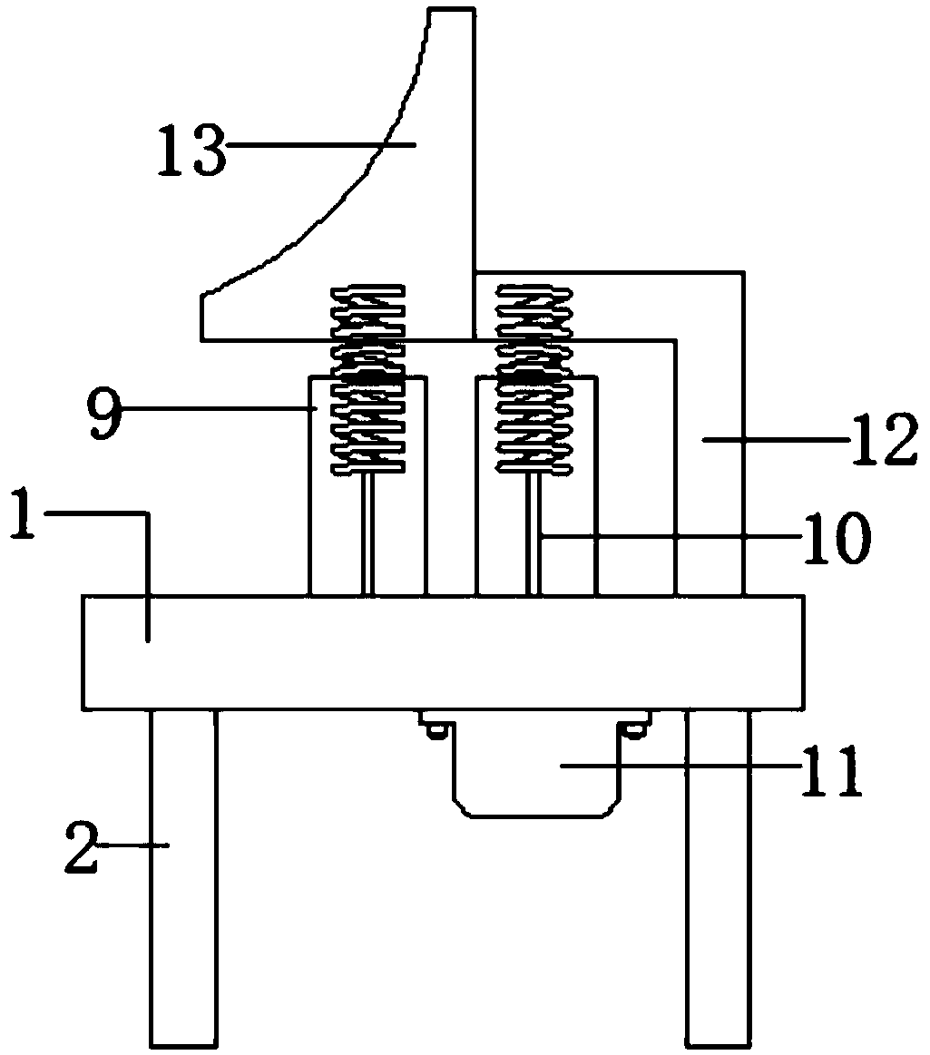
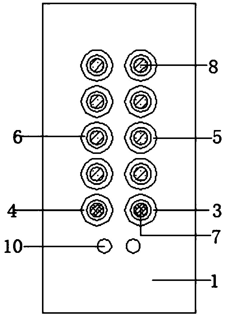
[0018] see Figure 1-3 , the present invention provides a technical solution: a bridge cover flanging device, including a workbench 1, a foot 2 and a motor 11, the foot 2 is welded on the left and right sides of the bottom of the workbench 1, and the motor 11 is connected by a bolt screw Connected to the right side of the bottom of the workbench 1, the left and right sides of the workbench 1 body are symmetrically embedded with the second bearing 4 and the fir...


PUM


Abstract

The invention belongs to the technical field of bridge cover plate production, and particularly discloses a bridge cover plate flanging device and a bridge cover plate machining method. The bridge cover plate flanging device comprises a workbench, stand bars and a motor; a first bearing and a second bearing are symmetrically embedded in the left side and the right side of a workbench body, third bearings are uniformly and longitudinally embedded in the right side of the workbench body, and fourth bearings are uniformly and longitudinally embedded in the left side of the workbench body; the outer wall of the first rotary shaft and the outer wall of the second rotary shaft are sleeved with rotary rollers; a right-angle supporting plate is welded to the right side of the top of the workbench;and a spiral baffle is welded to the left end of the right-angle supporting plate. A machining method of the bridge cover plate flanging device comprises the specific following steps that S1, a coverplate is put between the two rotary rollers to be clamped, and S2, the device is started so that the cover plate can move backwards at the constant speed, the cover plate is limited by the spiral baffle, and accordingly, flanging is conducted on the cover plate. Through the scheme, the machining steps are simplified, and the machining efficiency and the product percent of pass are improved.

Description

technical field [0001] The invention relates to the technical field of bridge cover plate production, in particular to a bridge cover plate flanging device and a bridge cover plate processing method. Background technique [0002] With the development of science and technology and the improvement of people's aesthetics, the processing requirements for bridges are getting higher and higher. More and more high-end projects pay more attention to the protection of cables. During the production process of existing bridges, cover plates need to be For flanging treatment, the commonly used methods are split welding or mold stamping, but there are problems such as not beautiful enough, easy to deform, high cost and long processing cycle. At the same time, a few flanging devices used for bridge cover plates need to be used Manually preset a flanging section at the end of the cover plate to facilitate alignment with the entrance of the bridge cover plate flanging device. The processing...

Claims


Application Information

Patent Timeline
Patent Type & Authority Applications(China)
IPC IPC(8): B21D19/00
Inventor 涂俊涂加福
Owner 天长市福骏金属制品有限公司
Why Eureka
Try Eureka