Automatic nozzle deburring and flow adjusting method

A flow regulation and deburring technology, applied in used abrasive treatment devices, abrasives, metal processing equipment, etc., can solve problems such as aero-engine safety that affects flow stability, lack of good removal methods, and low efficiency. , to achieve the effect of good consistency, complete burr removal and high flow regulation efficiency

Active Publication Date: 2019-03-08
SHENYANG LIMING AERO-ENGINE GROUP CORPORATION
View PDF7 Cites 3 Cited by
  • Summary
  • Abstract
  • Description
  • Claims
  • Application Information

AI Technical Summary

Problems solved by technology

[0003] At present, the fuel nozzle of an aero-engine is assembled from nearly 10 parts, and there are two main and auxiliary oil passages on the nozzle. At this stage, the burrs on the nozzle oil passage are usually removed manually, but for the inner hole and internal intersection on the nozzle oil passage There is no good way to remove the burrs at the holes. If the burrs at the inner holes and inner cross holes on the nozzle oil road cannot be completely removed, it will directly affect the flow stability and the safety of the aero-engine.
At the same time, due to the strict requirements on the outlet flow of the nozzle, it is necessary to adjust the flow of the nozzle. The current method can only be disassembled first, and then the size of the individual parts is adjusted separately, and finally the flow can be adjusted. However, the above flow adjustment methods are not only inefficient, but also poor in consistency

Method used


Image

  • Automatic nozzle deburring and flow adjusting method
  • Automatic nozzle deburring and flow adjusting method

Examples


Embodiment Construction

[0028] The present invention will be further described in detail below in conjunction with the accompanying drawings and specific embodiments.

[0029] A method for automatic nozzle deburring and flow adjustment, comprising the following steps:

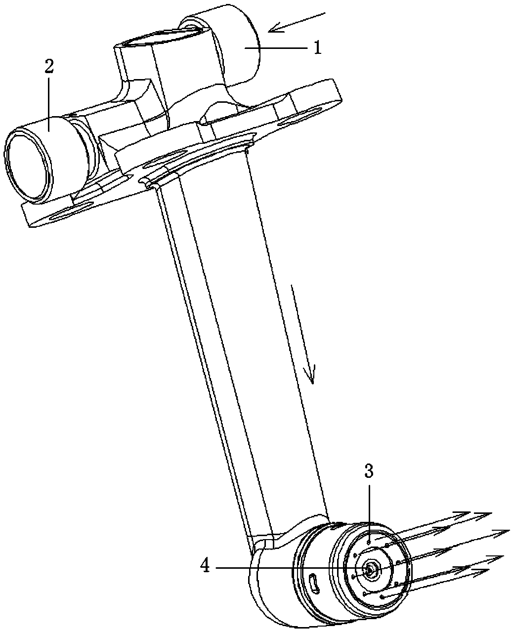
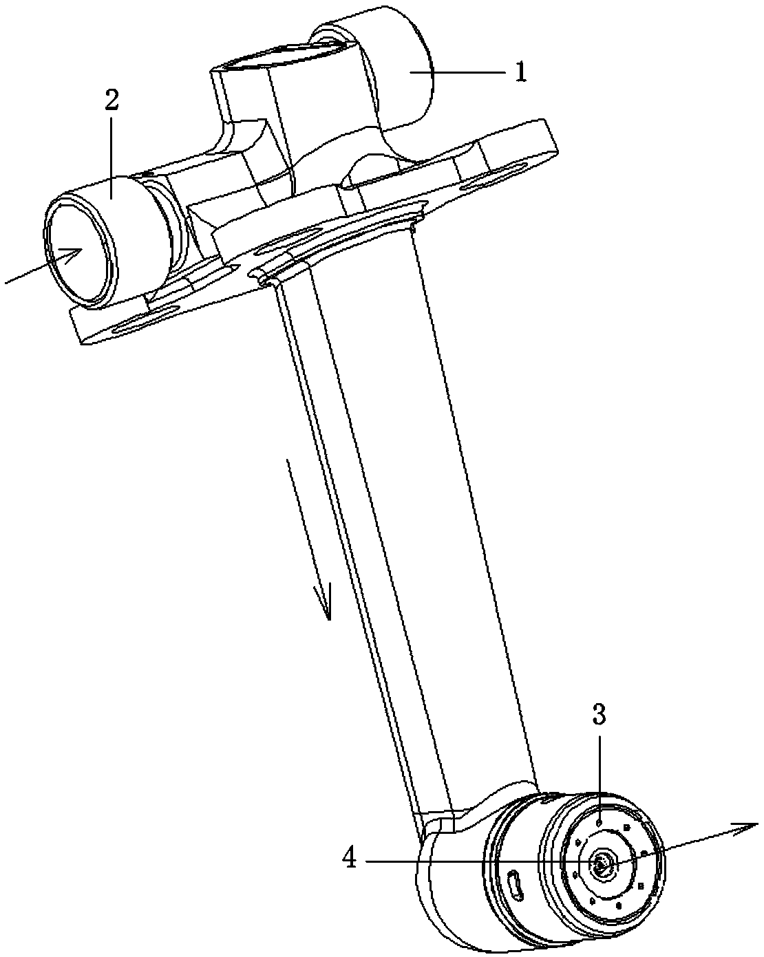
[0030] Step 1: Detect the initial flow of the nozzle through the special detection equipment for nozzle flow, and record the initial flow values ​​of the main fuel injection port 3 and the auxiliary fuel injection port 4 respectively;

[0031] Step 2: Use abrasive flow equipment to process the main oil circuit of the nozzle, first connect the main oil inlet 1 with the abrasive flow output port of the abrasive flow equipment, and then press figure 1 The flow direction shown is to feed the water-based abrasive flow into the nozzle, and the flow direction of the water-based abrasive flow in the nozzle needs to be consistent in one direction, and the burrs on the main oil road of the nozzle are removed by the water-based abrasive flow; th...


PUM


Abstract

An automatic nozzle deburring and flow adjusting method comprises the steps that the initial flow value of a main/auxiliary oil spraying port of each nozzle is measured; grinding particle flow equipment is utilized for machining a main/auxiliary oil path of each nozzle, and burrs on each main/auxiliary oil path are removed; cleaning fluid is utilized for cleaning the main/auxiliary oil path of each nozzle; the cleaning fluid is utilized for cleaning the grinding particle flow equipment; the nozzle flow after machining is detected and then compared with the initial flow value, and the grindingparticle flow machining time and flow changing relation under corresponding machining parameters is determined; for nozzles with small flow, secondary grinding particle flow machining is conducted onthe nozzles according to the obtained grinding particle flow machining time and flow changing relation, the nozzle flow is further adjusted till the flow of all the nozzles is consistent, and the flowrequirement is met; the grinding particle flow equipment is cleaned; ultrasonic cleaning equipment is utilized for nozzle cleaning, and residual cleaning fluid is removed; and the weight of each nozzle is measured and compared with the initial weight of the nozzle before grinding particle flow machining, and it is ensured that the nozzle weight changing value does not exceed 50 g.

Description

technical field [0001] The invention belongs to the technical field of aero-engine component manufacturing, in particular to an automatic nozzle deburring and flow regulating method. Background technique [0002] The fuel nozzle of an aero-engine is a key component for propelling fuel combustion, which has an important impact on the fuel efficiency and power performance of an aero-engine. The internal structure of the fuel nozzle is complex and there are many parts. It is necessary to precisely control the dimensional accuracy of each part inside the nozzle to accurately control the flow of fuel and improve combustion efficiency. [0003] At present, the fuel nozzle of an aero-engine is assembled from nearly 10 parts, and there are two main and auxiliary oil passages on the nozzle. At this stage, the burrs on the nozzle oil passage are usually removed manually, but for the inner hole and internal intersection on the nozzle oil passage There is no good way to remove the burr...

Claims


Application Information

Patent Timeline
Patent Type & Authority Applications(China)
IPC IPC(8): B24C1/08B24C7/00B24C9/00B24C11/00
CPCB24C1/083B24C7/0023B24C9/00B24C11/00
Inventor 单坤周雨辰张亚双于武
Owner SHENYANG LIMING AERO-ENGINE GROUP CORPORATION
Why Eureka
Try Eureka