Mold cutting roller device with waste discharging function

A die-cutting knife and knife roller technology, which is applied in metal processing and other directions, can solve the problems of chipping, easy accumulation and jamming of waste materials, and affect the integrity of cut products, so as to achieve the effect of prolonging the service life

Inactive Publication Date: 2019-03-08
苏州中航盛世刀辊制造有限公司
View PDF6 Cites 1 Cited by
  • Summary
  • Abstract
  • Description
  • Claims
  • Application Information

AI Technical Summary

Problems solved by technology

[0003] Because the rotary die-cutting machine will produce waste when cutting the product, the waste is easy to accumulate and get stuck in the cutting edge of the die-cutting knife roller after repeated roll cutting. If there is no space to avoid the cutting edge, it will be squeezed and collapse. The phenomenon of the edge, which directly affects the integrity of the cut product

Method used


Image

  • Mold cutting roller device with waste discharging function
  • Mold cutting roller device with waste discharging function

Examples


Embodiment

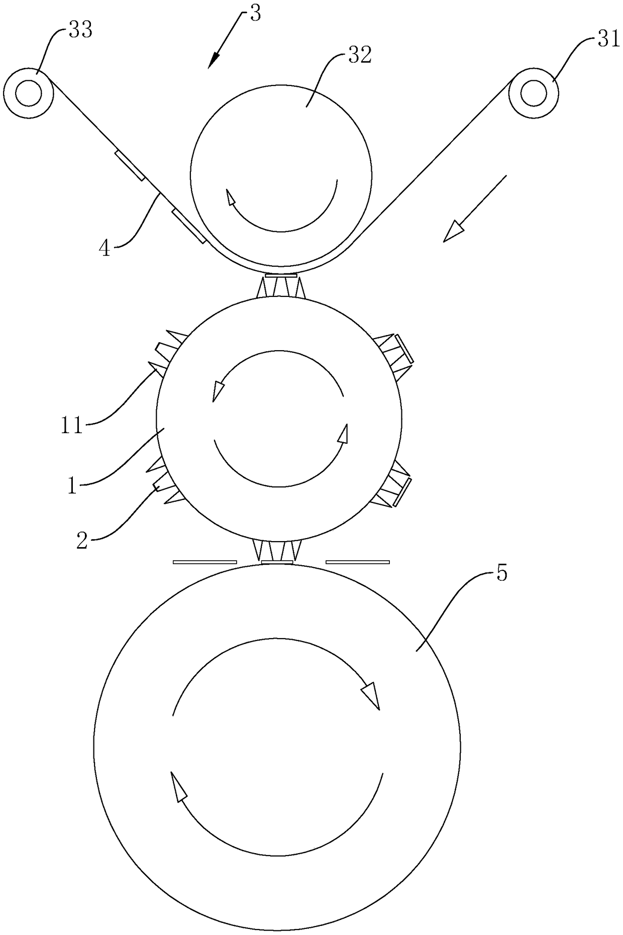
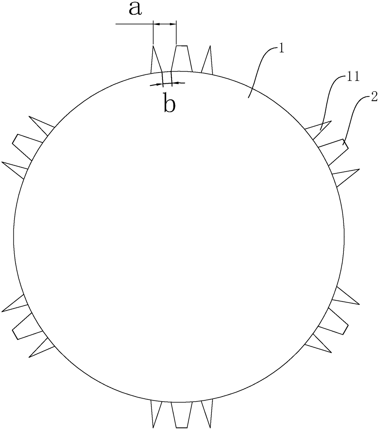
[0033] Such as figure 1 As shown, it is a die-cutting knife roll device with a waste discharge function disclosed in the present invention, which includes a knife roll body 1 and a steel roll 5 . The knife roll body 1 is located directly above the steel roll 5, and the two can be synchronously driven by gears (not shown) mounted on respective shaft ends. Several cutting edges 11 are arranged on the surface of the knife roller body 1, and the cutting edges 11 are milled out and shaped by a milling machine, and the material to be die-cut is sent to the knife roller body 1 and the steel roller 5 through other conveying rollers (not shown in the figure). between, and through the cutting edge 11 for die-cutting. In specific production, the material to be die-cut can be cardboard or PET, PE and other films.

[0034] Such as figure 1 As shown, on the knife roller body 1, a waste lifting block 2 is arranged between two adjacent cutting edges 11, and the end surface of the waste lif...


PUM


Abstract

The invention discloses a mold cutting roller device with a waste discharging function, and belongs to the field of mold cutting rollers. The mold cutting roller device comprises a cutting roller bodyand a plurality of cutting edges arranged on the surface of the cutting roller body. A waste extracting block is arranged between every two adjacent cutting edges and on the cutting roller body. Theheight of the waste extracting blocks is less than that of the cutting edges. A plurality of pattern grooves used for pasting waste are formed in the end faces, away from the cutting roller body, of the waste extracting blocks. Waste pasting assemblies used for pasting the surfaces of the pattern grooves are arranged above the cutting roller body. The mold cutting roller device has the effects that waste produced in mold cutting can be pasted, other pasting materials are matched to automatically discharge the waste to protect the cutting edges.

Description

technical field [0001] The invention relates to the technical field of a die-cutting knife roll, in particular to a die-cutting knife roll device with a waste discharge function. Background technique [0002] Rotary die cutting machine is a cutting machine widely used in printing, mobile phone accessories manufacturing, paper packaging, non-woven fabrics and other industries. The working parts of the plate table and the press-cutting mechanism of the rotary die-cutting machine are both cylindrical. When working, the paper feed roller sends the cardboard or film between the mold plate cylinder and the pressure cylinder, and the two press it. Clamp and die-cut the cylinder with a die-cutting knife roller with a cutting edge, and the die-cutting plate cylinder rotates once for a working cycle. [0003] Because the rotary die-cutting machine will produce waste when cutting the product, the waste is easy to accumulate and get stuck in the cutting edge of the die-cutting knife ro...

Claims


Application Information

Patent Timeline
Patent Type & Authority Applications(China)
IPC IPC(8): B26F1/44B26D7/18
CPCB26D7/18B26F1/44
Inventor 周立国王奇王晓阳刘晓磊张燕青
Owner 苏州中航盛世刀辊制造有限公司
Why Eureka
Try Eureka