Radius end mill, ball end mill, and end mill

A technology of end mills and arc heads, which is applied in the field of end mills with arc heads, which can solve the problems of smaller tool angles and inability to ensure the strength of the tool tip, so as to increase the cutting speed, prevent the tool from chipping, and improve the strength of the tool tip Effect

Inactive Publication Date: 2017-08-01
MITSUBISHI MATERIALS CORP
View PDF11 Cites 1 Cited by
  • Summary
  • Abstract
  • Description
  • Claims
  • Application Information

AI Technical Summary

Problems solved by technology

[0027] However, when the ball end mill is made of ceramics, if the radial rake angle of the outer peripheral cutting edge is increased toward the positive angle side, as described above, the tool angle becomes small and the edge strength cannot be ensured.

Method used


Image

  • Radius end mill, ball end mill, and end mill
  • Radius end mill, ball end mill, and end mill
  • Radius end mill, ball end mill, and end mill

Examples


no. 1 Embodiment approach >

[0111] Hereinafter, a first embodiment of an end mill according to the present invention will be described with reference to the drawings.

[0112] In the first embodiment, a radius end mill will be described as an example of an end mill.

[0113] 〔Basic structure of arc-end end mill and main body of end mill〕

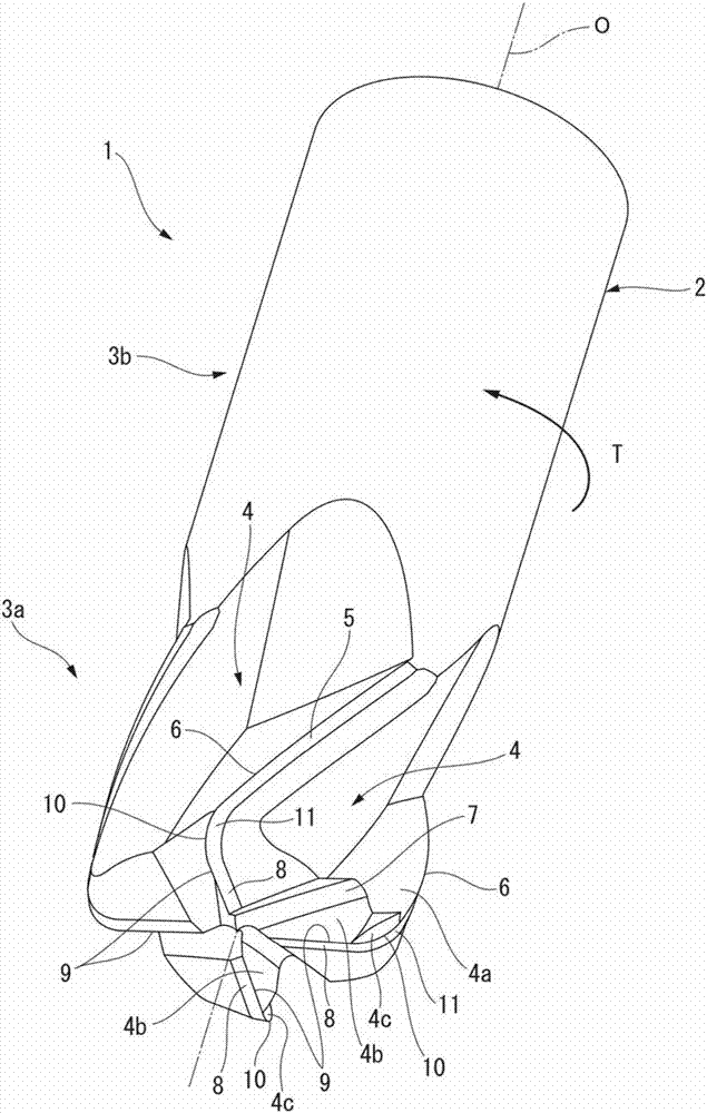
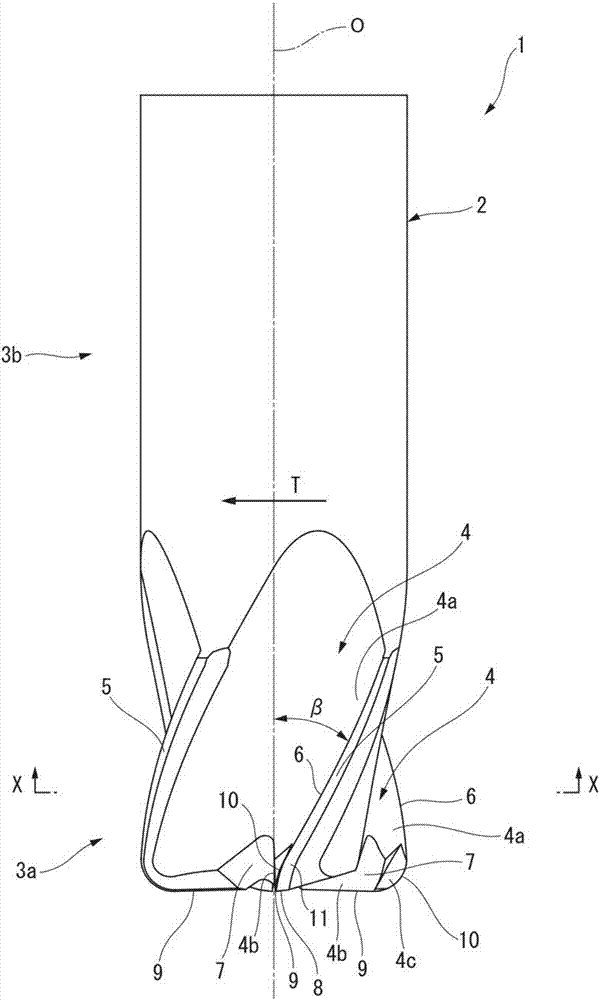
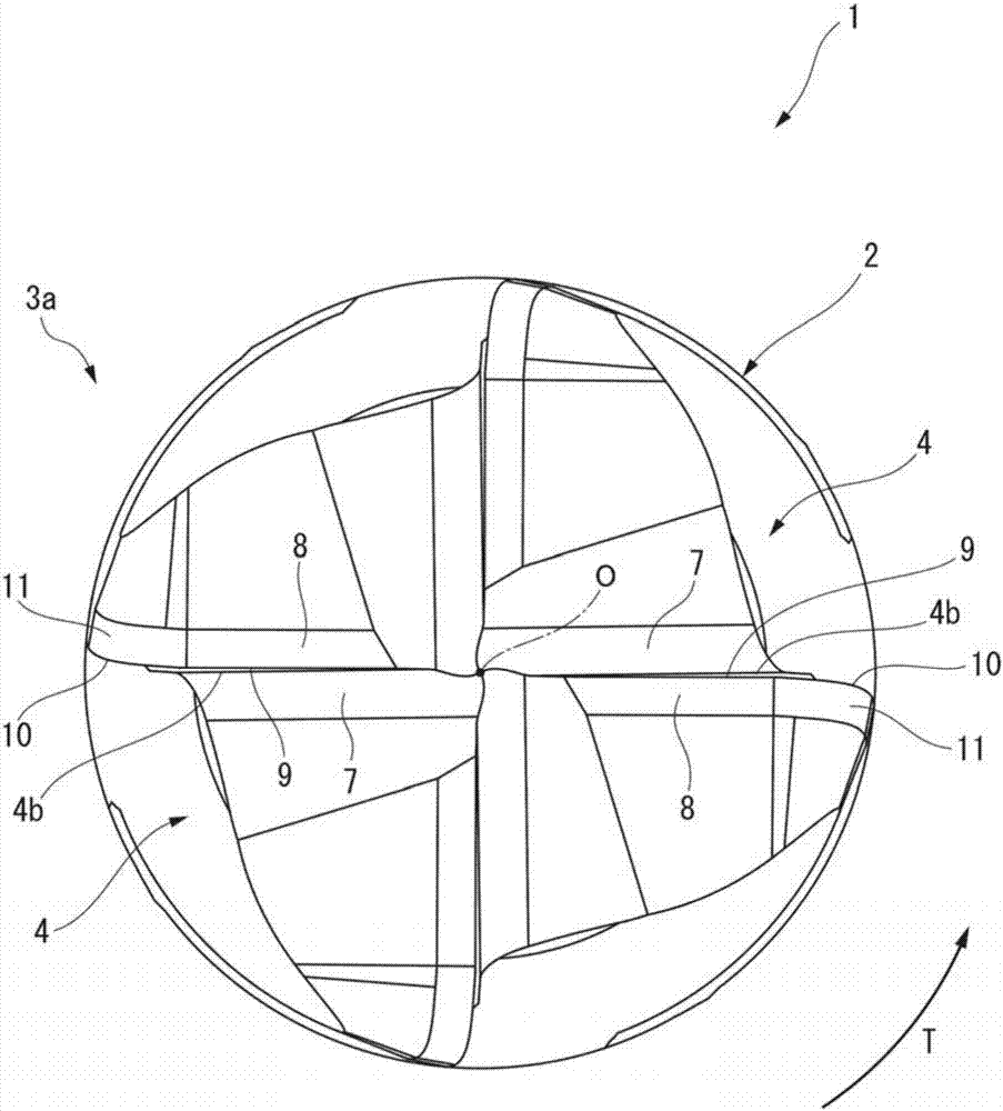
[0114] Such as Figure 1 ~ Figure 3 As shown, the arcuate end mill 1 of this embodiment has a shaft-shaped end mill body 2 made of ceramics. Specifically, the end mill body 2 is made of ceramic material Sialon (SiAlON).

[0115] The end mill body 2 has a substantially cylindrical shape, and a cutting edge portion 3 a is formed at least at a front end portion of the end mill body 2 along the axis O direction. A portion of the end mill body 2 other than the blade portion 3a is a shank portion 3b.

[0116] With regard to the arc nose end mill 1, the cylindrical shank portion 3b in the end mill main body 2 is held by the spindle of the machine tool or the like, and rot...

no. 2 Embodiment approach >

[0226] Next, refer to Figure 6 ~ Figure 9 A second embodiment of the end mill according to the present invention will be described.

[0227] In addition, in the second embodiment, a ball end mill will be described as an example of the end mill.

[0228] [Basic structure of ball nose end mill and end mill body]

[0229] Such as Figure 6 ~ Figure 8As shown, the ball end mill 101 of this embodiment has a shaft-shaped end mill body 102 made of ceramics. Specifically, the end mill body 102 is made of ceramic material Sialon (SiAlON).

[0230] The end mill body 102 has a substantially cylindrical shape, and a cutting edge portion 103 a is formed at least at a front end portion of the end mill body 102 along the axis O direction. The portion of the end mill body 102 other than the blade portion 103a is a shank portion 103b.

[0231] Regarding the ball end mill 101, the cylindrical shank portion 103b in the end mill main body 102 is held by the spindle of the machine tool or th...

no. 3 Embodiment approach >

[0307] Next, refer to Figure 11 to Figure 14 A third embodiment of the end mill according to the present invention will be described.

[0308] In addition, in the third embodiment, a tapered ball end mill which is a kind of ball end mill is exemplified as an end mill and described. In this third embodiment, detailed descriptions of the same constituent elements as those of the second embodiment will be omitted, and only differences will be mainly described below.

[0309] [Differences from the second embodiment]

[0310] Such as Figure 11 ~ Figure 13 As shown, in the ball end mill 111 of this embodiment, the central groove 107 is formed in the shape of a trapezoidal cross-sectional trapezoidal groove extending radially at the front end portion of the flute 104 , and the radially inner end of the central groove 107 part reaches the axis O.

[0311] In this embodiment, four center grooves 107 are formed corresponding to the four flutes 104 . These central grooves 107 comm...


PUM


Abstract

The present invention is provided with: a ceramic end mill main body (2); chip discharge grooves (4) formed in an outer periphery of the end mill main body (2); outer peripheral cutting edges (6) formed at intersecting ridge lines between wall surfaces which face in a tool rotation direction (T), in the chip discharge grooves (4), and an outer peripheral surface of the end mill main body (2); base cutting edges formed at intersecting ridge lines between the wall surfaces in the chip discharge grooves (4) and a tip end surface of the end mill main body (2); and corner cutting edges which are located in tip end outer peripheral portions of the end mill main body (2), connect the outer ends of the base cutting edges with the tip ends of the outer peripheral cutting edges (6), and are formed in the shape of convex curved lines which have a convexity facing toward the tip end outer peripheral side of the end mill main body (2). From among the outer peripheral cutting edges (6), the base cutting edges and the corner cutting edges, a radial rake angle (angle alpha) of at least the outer peripheral cutting edges (6) is set to a negative angle. The radial rake angle (angle alpha) of the outer peripheral cutting edges (6) is between -20 deg and -10 deg.

Description

technical field [0001] The invention relates to a circular arc head end mill made of ceramics. [0002] This application claims priority based on Patent Application No. 2015-038218 filed in Japan on February 27, 2015 and Patent Application No. 2015-038219 filed in Japan on February 27, 2015, and the contents thereof are incorporated herein. Background technique [0003] Conventionally, for example, a circular arc end mill made of ceramics as disclosed in Patent Document 1 is known. [0004] This arcuate end mill has a shaft-shaped end mill body, and chip flutes, peripheral cutting edges, bottom cutting edges (tip cutting edges), and edge corners are formed on the end mill cutting body. [0005] During the cutting process, the arc nose end mill is rotated toward the tool rotation direction in the circumferential direction around the axis of the end mill body and is fed (feed) toward the direction intersecting the axis, thereby cutting into the workpiece material. [0006] S...

Claims


Application Information

Patent Timeline
Patent Type & Authority Applications(China)
IPC IPC(8): B23C5/10B23C5/16
CPCB23C5/10B23C5/1009B23C2210/0435B23C2210/0485B23C2210/082B23C2226/18B23C2210/0421B23C2210/203B23C2210/40B23C5/16
Inventor 渡边博史坂口光太郎
Owner MITSUBISHI MATERIALS CORP
Why Eureka
Try Eureka