A probe interface circuit and a probe adaptation circuit for a probe of an oscilloscope

A technology of interface circuits and oscilloscopes, applied in the direction of instruments, measuring electrical variables, digital variable display, etc., can solve problems such as limitations, unfavorable expansion identification, and increased risk of poor contact of connectors, so as to meet electricity demand and avoid interference The effect of action

Active Publication Date: 2020-08-11
SHENZHEN CITY SIGLENT TECH
View PDF2 Cites 0 Cited by
  • Summary
  • Abstract
  • Description
  • Claims
  • Application Information

AI Technical Summary

Problems solved by technology

However, there are still some problems when using this circuit for probe adaptation connection: (1) The bias signal is directly connected to the active probe through the connector on the oscilloscope, so that the transmission process of the bias signal is exposed to the environment, and it is vulnerable to environmental electromagnetic interference. interference; (2) Both active probe identification and passive probe identification are identified through high level and low level, which limits the types of identifiable probes and is not conducive to the need for extended identification; (3) using a The 9-pin connector increases the risk of poor contact of the connector

Method used


Image

  • A probe interface circuit and a probe adaptation circuit for a probe of an oscilloscope
  • A probe interface circuit and a probe adaptation circuit for a probe of an oscilloscope
  • A probe interface circuit and a probe adaptation circuit for a probe of an oscilloscope

Examples


Embodiment 1

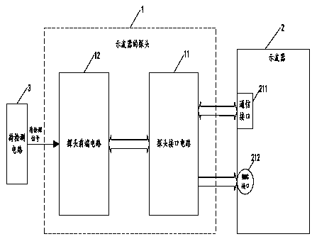
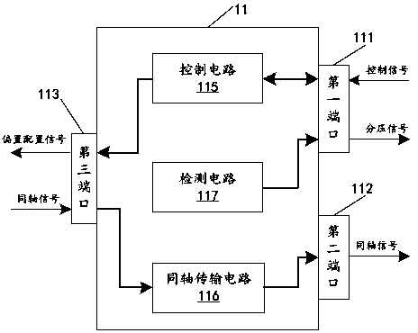
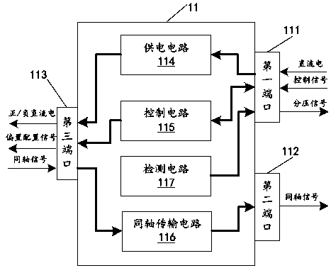
[0034] Please refer to figure 1 and figure 2 , the present application discloses a probe interface circuit for a probe of an oscilloscope, wherein the oscilloscope 2 includes a communication interface 211 and a BNC interface 212, and the probe 1 includes a probe interface circuit 11 and a probe front-end circuit 12, and the probe interface circuit 11 claimed here includes The control circuit 115, the detection circuit 117 and the coaxial transmission circuit 116 are respectively described as follows.

[0035] The control circuit 115 has an input end and an output end, and the input end of the control circuit 115 is used to connect with the communication interface 211 of the oscilloscope 2 and receive the control signal generated by the oscilloscope 2 (see figure 2 The control signal shown in ), and the input terminal of the control circuit 115 is used to configure the DC bias according to the received control signal to generate a bias configuration signal (see figure 2 Th...

Embodiment 2

[0070] Please refer to Figure 9 , the present application requests protection of a probe adaptation circuit 21 of an oscilloscope, the probe adaptation circuit 21 may include a communication interface 211, a BNC interface 212, a power supply circuit 213, an identification circuit 214, a processor 215 and an impedance circuit 216, which will be described separately below .

[0071] The communication interface 211 and the BNC interface 212 are respectively adapted to be connected to the first port 111 and the second port 112 of the probe interface circuit 11 disclosed in the first embodiment.

[0072] The power supply circuit 213 is connected to the communication interface 211 for outputting direct current through the communication interface 211 . For example, the output of the first level of direct current can include +12V, -12V and 0V.

[0073] The identification circuit 214 includes an analog-to-digital converter U1, the input end of the analog-to-digital converter U1 is c...

Embodiment 3

[0084] In order to better help those skilled in the art understand the technical solutions provided in this embodiment, the probe interface circuit 11 and probe front-end circuit 12 disclosed in Example 1 and the probe adaptation circuit 21 disclosed in Example 2 are used here Composition of the signal detection system, combined with figure 1 , image 3 , Figure 8 and Figure 9 Explain in detail how the technical solution works.

[0085] see figure 1 , image 3 and Figure 8 , the probe 1 of the oscilloscope includes a probe interface circuit 11 and a probe front-end circuit 12, the probe interface circuit 11 is adapted to be connected to the communication interface 211 of the oscilloscope 2 through its first port 111, and the second port 112 of the probe interface circuit 11 is adapted to be connected to The BNC interface 212 of the oscilloscope 2 and the third port 113 of the probe interface circuit 11 are connected to the fourth port 121 of the probe interface circui...


PUM


Abstract

A probe interface circuit and a probe adaptation circuit for a probe of an oscilloscope, wherein the probe includes a probe interface circuit and a probe front-end circuit, the probe interface circuit includes a control circuit, a detection circuit and a coaxial transmission circuit; The communication interface of the oscilloscope receives the control signal generated by the oscilloscope, and configures the DC offset according to the control signal to generate the offset configuration signal, and outputs the offset configuration signal to the probe front-end circuit through its output terminal, so that the probe front-end circuit is in the Under the action of the bias configuration signal, the DC bias is superimposed on the signal to be detected, and the coaxial signal with the output impedance matching the BNC interface of the oscilloscope is generated through attenuation adjustment and impedance adjustment. Since the probe interface circuit can generate the offset configuration signal according to the control signal, it is beneficial to realize the free superposition of the DC offset of the signal to be detected, and overcome the functional deficiencies of the existing oscilloscope probe.

Description

technical field [0001] The invention relates to the technical field of oscilloscopes, in particular to a probe interface circuit and a probe adaptation circuit for a probe of an oscilloscope. Background technique [0002] An oscilloscope probe is a device that connects the signal under test to the input of the oscilloscope. Its performance is crucial to the accuracy and correctness of the measurement results. It is essentially an electronic component that connects the circuit under test to the input of the oscilloscope. The simplest probe is a wire connecting the circuit under test and the input end of the electronic oscilloscope. Since no shielding measures are taken, it is easy to be interfered by the external electromagnetic field, and its equivalent capacitance is large, which will easily increase the load of the circuit under test; however, Complex probes consist of RC elements and active devices. Oscilloscope probes can generally be divided into active probes and pass...

Claims


Application Information

Patent Timeline
Patent Type & Authority Patents(China)
IPC IPC(8): G01R13/02
CPCG01R13/0218
Inventor 林辉浪邝被华宋民
Owner SHENZHEN CITY SIGLENT TECH
Why Eureka
Try Eureka