
Stamping mechanism of stamping machine

A stamping machine and seal technology, which is applied in the field of stamping machines, can solve problems such as insufficient automation, manual position adjustment, and low stamping efficiency, so as to improve aesthetics and applicability, buffer anti-impact force, and improve use The effect of longevity

Pending Publication Date: 2019-03-08
SHANGHAI GOOAO ELECTRONIC TECHNOLOGY CORP
View PDF0 Cites 0 Cited by
  • Summary
  • Abstract
  • Description
  • Claims
  • Application Information

AI Technical Summary

Problems solved by technology

However, traditional stamping equipment needs manual intervention when faced with a large number of complex stamping requirements, especially when facing multiple stamps on a document, it is often necessary to replace the stamp and manually adjust the position. Stamping operation wastes a lot of time, and the efficiency of stamping is low, but the existing stamping machine still needs to manually adjust the position and angle, and the degree of automation is not high enough. Therefore, we propose a stamping mechanism of the stamping machine. to solve the above problems

Method used


Image

  • Stamping mechanism of stamping machine
  • Stamping mechanism of stamping machine
  • Stamping mechanism of stamping machine

Examples


Embodiment Construction

[0018] The following will clearly and completely describe the technical solutions in the embodiments of the present invention with reference to the accompanying drawings in the embodiments of the present invention. Obviously, the described embodiments are only some, not all, embodiments of the present invention. Based on the embodiments of the present invention, all other embodiments obtained by persons of ordinary skill in the art without making creative efforts belong to the protection scope of the present invention.

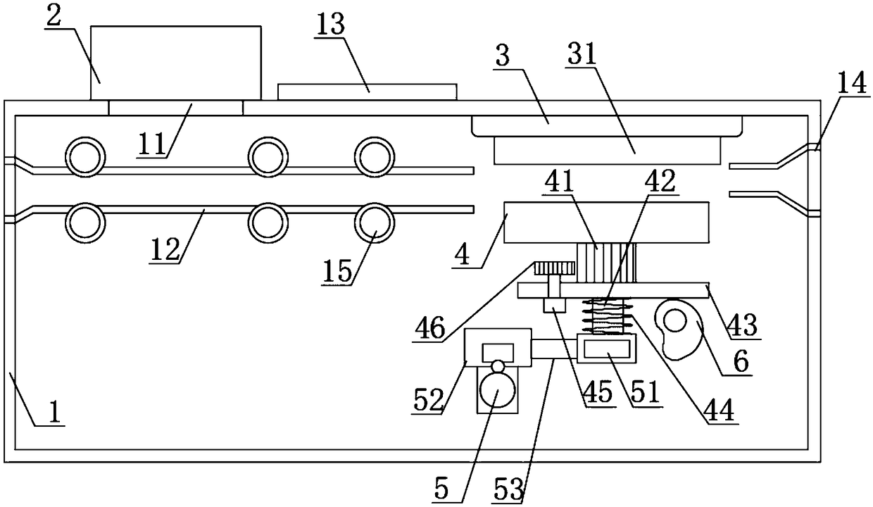
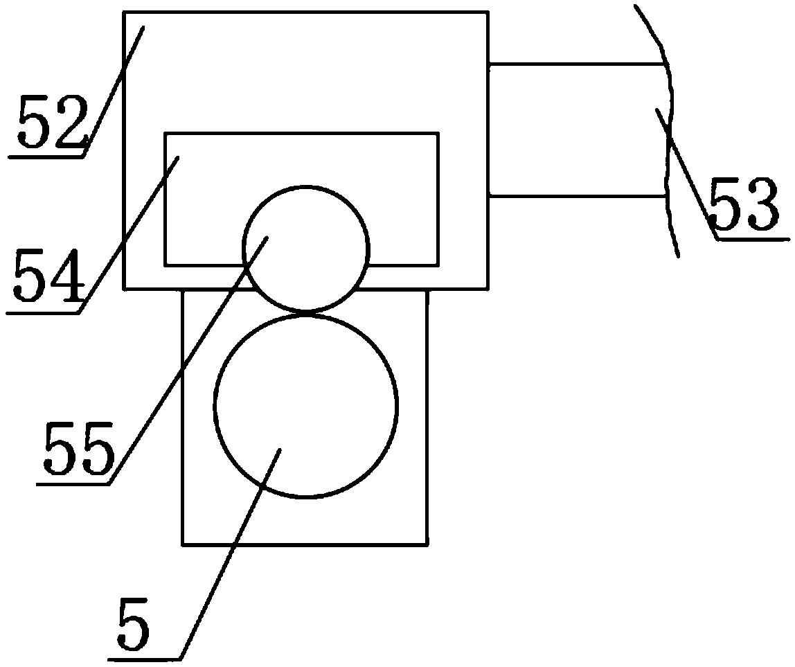
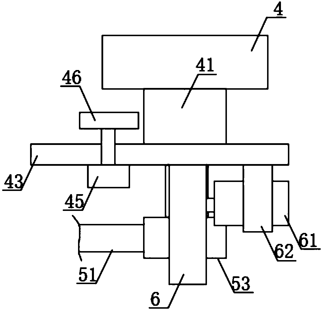
[0019] see Figure 1-5 , the present invention provides a technical solution: a stamping mechanism of a stamping machine, comprising a mechanism frame 1, a screw rod 5 and a rectangular slide bar 51, the upper end of the mechanism frame 1 is provided with a transparent window 11, the transparent window 11 is tempered The glass plate, the upper end of the transparent window 11 is fixedly connected with the camera mechanism 2, the middle part of the lower end of...


PUM


Abstract

The invention discloses a stamping mechanism of a stamping machine. The stamping mechanism of the stamping machine comprises a mechanism frame, a lead screw and a rectangular sliding rod. A transparent window is formed in the upper end of the mechanism frame, and a shooting mechanism is fixedly connected with the upper end of the transparent window. A liquid crystal touch panel is fixedly connected with the middle of the upper end of the mechanism frame. A paper guide groove is fixedly connected with the left side of an inner cavity of the mechanism frame, and paper guide wheels are movably connected with the inner side of the paper guide groove in a clamped mode. A paper outlet groove is fixedly connected with the right side of the inner cavity of the mechanism frame. A shock pad is fixedly connected with the right portion of the upper side of the inner cavity of the mechanism frame, and a stamp pad is fixedly connected with the lower end of the shock pad. The lead screw is fixedly connected with the middle of the inner cavity of the mechanism frame, and a sliding mechanism sleeves the upper end of the lead screw in a connected mode. A reset spring sleeves the outer side of a telescopic rod in a connected mode, an installation base plate is fixedly connected with the upper end of the telescopic rod, and a stamp is fixedly connected with the upper end of the installation base plate through a connecting column. The stamping mechanism can accurately judge and adjust the angle and the position of the stamp and conduct accurate stamping.

Description

technical field [0001] The invention relates to the technical field of stamping machines, in particular to a stamping mechanism of the stamping machine. Background technique [0002] Seal, English stamp, also known as seal, is used as a stationery printed on documents to indicate identification or signature. Generally, stamps are first stained with paint and then printed. Those that do not stick with paint and will appear uneven after being printed on a plane are called steel seals. Some A wax seal made on wax or wax, on envelopes. Materials include metal, wood, stone, jade, etc. In today's society, seals are still an important means of identification that cannot be ignored, and are often used in banks and other institutions. [0003] With the development of society and the increase of people's mobility, the workload of some government departments has greatly increased. Government departments will stamp the documents they handle, which greatly increases the workload of staf...

Claims


Application Information

Patent Timeline
Patent Type & Authority Applications(China)
IPC IPC(8): B41K3/26B41K3/62
CPCB41K3/26B41K3/62
Inventor 严陈贾超凡
Owner SHANGHAI GOOAO ELECTRONIC TECHNOLOGY CORP
Learn More