Multi-angle cutting and edging numerical control machine tool

A CNC machine tool, multi-angle technology, applied in the field of CNC machine tools, can solve the problems of reducing the processing efficiency of parts, shaking and offsetting parts, damage of parts, etc., to achieve the effect of convenient cutting operation, improving processing efficiency and improving stability

Pending Publication Date: 2022-08-02
杨炳森
View PDF4 Cites 0 Cited by
  • Summary
  • Abstract
  • Description
  • Claims
  • Application Information

AI Technical Summary

Problems solved by technology

[0002] Existing CNC machine tools can only process the target part at one angle when processing parts. It is necessary to frequently disassemble and reinstall the parts, and then process the parts at different angles, which reduces the efficiency of part processing. The use of manual hand-held parts is easy to cause production safety accidents, and after the parts are rotated, the parts are processed, the parts are prone to shaking and offset, and the probability of damage to the parts increases. At the same time, after the parts are cut, the parts need to be transferred Grinding at the grinding structure is a waste of time and reduces the efficiency of parts processing

Method used


Image

  • Multi-angle cutting and edging numerical control machine tool
  • Multi-angle cutting and edging numerical control machine tool
  • Multi-angle cutting and edging numerical control machine tool

Examples


Embodiment Construction

[0028] The technical solutions of the present invention will be clearly and completely described below with reference to the embodiments. Obviously, the described embodiments are only a part of the embodiments of the present invention, rather than all the embodiments. Based on the embodiments of the present invention, all other embodiments obtained by those of ordinary skill in the art without creative efforts shall fall within the protection scope of the present invention.

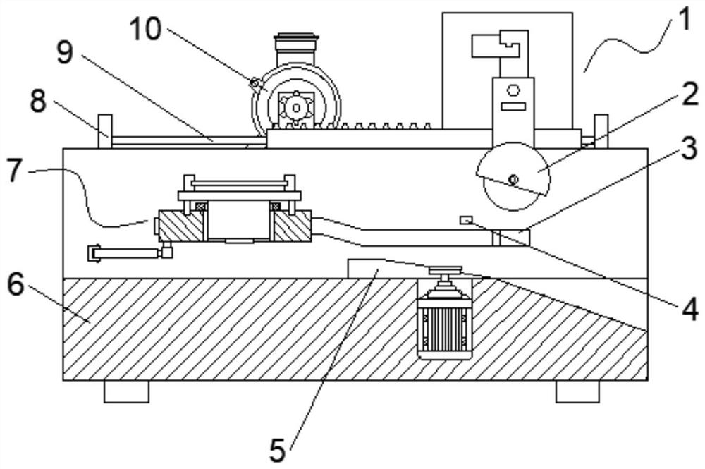
[0029] see figure 1 As shown, a multi-angle cutting and edging CNC machine tool includes a machine body 6, the top of the machine body 6 is provided with a working groove, the inner walls of both sides of the working groove are provided with a limit groove 3, and one end of the limit groove 3 is fixedly connected There is a baffle plate, a steering mechanism 7 is arranged inside the working groove, and a control mechanism 1 is arranged on the top of the machine body 6 .

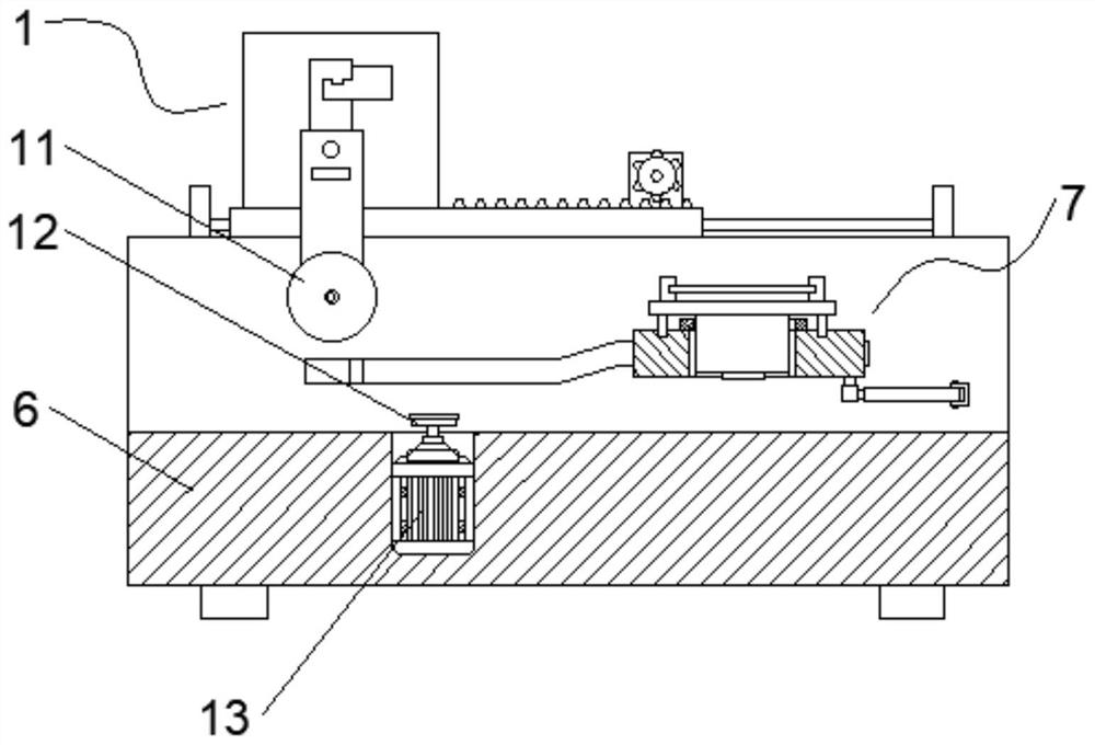
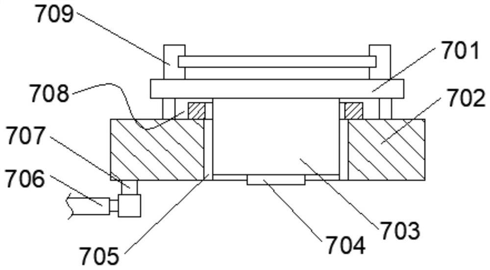
[0030] see figure 2 , image 3 ...


PUM


Abstract

The multi-angle cutting and edging numerical control machine tool comprises a machine tool body, a working groove is formed in the top of the machine tool body, limiting grooves are formed in the inner walls of the two sides of the working groove, a steering mechanism is arranged in the working groove, and the steering mechanism comprises a supporting plate; the four corners of the supporting plate are slidably connected with the corresponding limiting grooves through fixing pins, a rotating groove is formed in the top of the supporting plate, a rotating seat is rotatably connected to the inner wall of the rotating groove through a bearing, and an operation plate is fixedly connected to the top of the rotating seat; a supporting plate slides to a set position under the limiting condition of four fixing pins, a rubber plate abuts against an anti-skid plate, and a stepping motor operates to be matched with the anti-skid plate to drive a rotating base to rotate, so that a part on an operation plate is changed by a horizontal angle, and cutting equipment and grinding equipment can conveniently conduct cutting and edge grinding operation on the part by multiple angles; therefore, the machining efficiency of parts is improved.

Description

technical field [0001] The invention relates to the technical field of numerical control machine tools, in particular to a numerical control machine tool for multi-angle cutting and edging. Background technique [0002] When the existing CNC machine tools process parts, they can only process the target parts at one angle, and the parts need to be disassembled and installed frequently, and then the parts are processed at different angles, which reduces the efficiency of parts processing. The use of manual hand-held parts is easy to cause production safety accidents, and after the parts are rotated and then processed, the parts are prone to shaking and offset, which increases the probability of damage to the parts. At the same time, after the parts are cut, the parts need to be transferred. Grinding at the grinding structure is time-consuming and reduces the efficiency of parts processing. SUMMARY OF THE INVENTION [0003] The technical problems solved by this solution are:...

Claims


Application Information

Patent Timeline
Patent Type & Authority Applications(China)
IPC IPC(8): B23P23/04B23Q7/00
CPCB23P23/04B23Q7/00Y02P70/10
Inventor 杨炳森陈伟昌
Owner 杨炳森
Why Eureka
Try Eureka