Crank and sliding block-based train decoupling equipment

A crank slider and train technology, which is applied to railway car body components, railway vehicle coupling accessories, railway couplings, etc., can solve the problems of high work intensity, low reliability, low efficiency, etc., and achieve convenient operation, Strong reliability and high degree of action completion

Inactive Publication Date: 2019-03-08
CHINA UNIV OF GEOSCIENCES (WUHAN)
View PDF11 Cites 9 Cited by
  • Summary
  • Abstract
  • Description
  • Claims
  • Application Information

AI Technical Summary

Problems solved by technology

[0004] In order to solve the above-mentioned technical problems, the object of the present invention is to provide a train decoupling device based on the slider crank to solve the existing defects of high working intensity, low efficiency and low reliability.

Method used


Image

  • Crank and sliding block-based train decoupling equipment
  • Crank and sliding block-based train decoupling equipment
  • Crank and sliding block-based train decoupling equipment

Examples


Embodiment 1

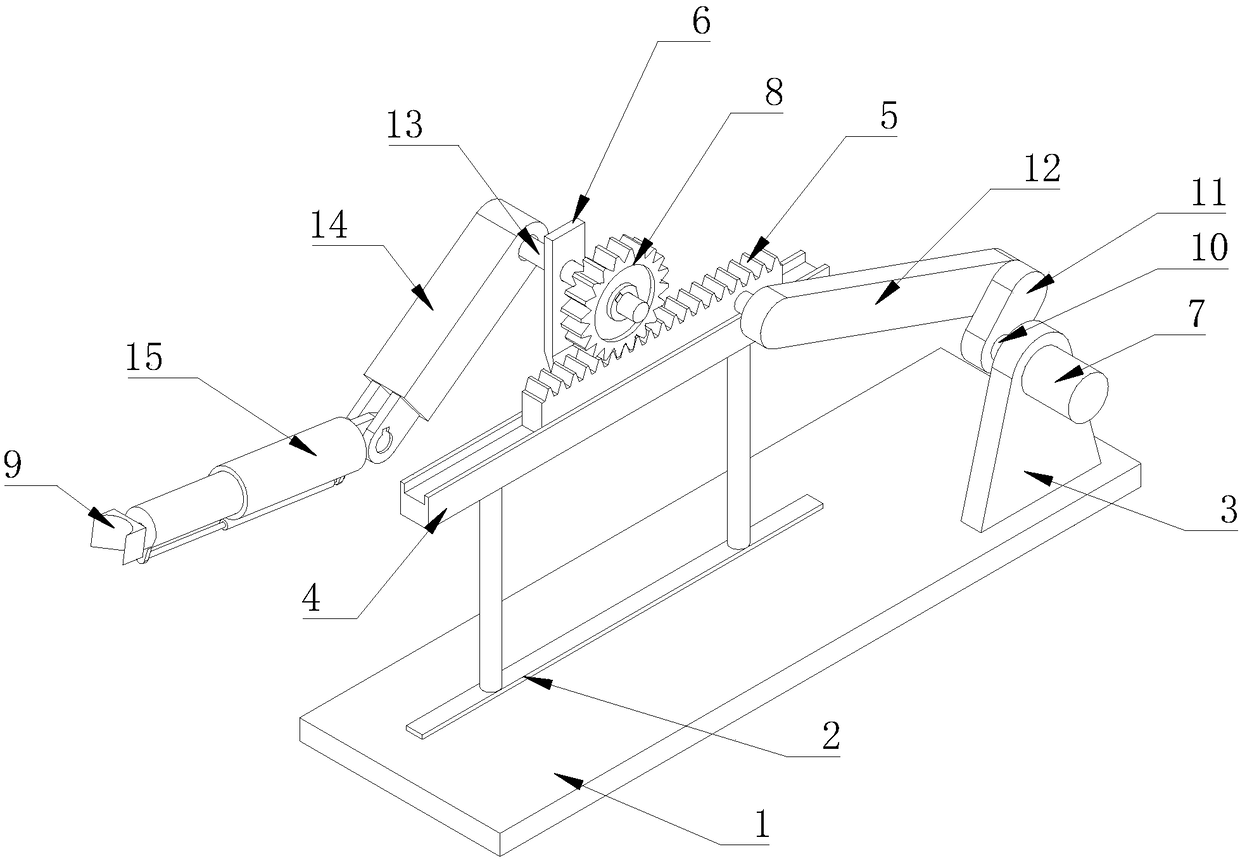
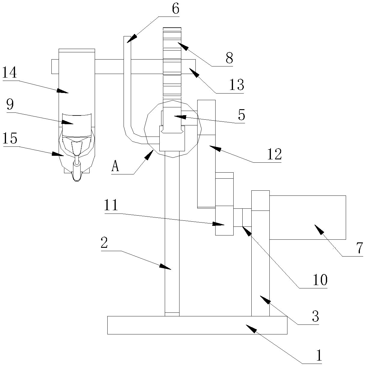
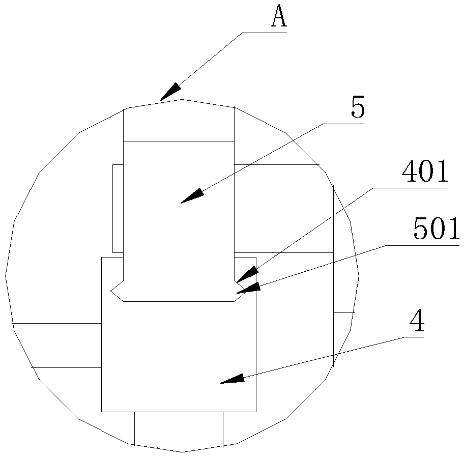
[0026] Please refer to figure 1 , figure 2 and image 3 , the present invention provides a train decoupling device based on a crank slider, comprising a base 1, a bracket 2 and a fixed support plate 3, the bracket 2 can be two poles arranged parallel to the length direction of the base 1, and the The fixed support plate 3 and the support 2 are all vertically fixed on the base 1, and a horizontal chute 4 is fixed on the top of the support 2, and a tooth along the length direction is respectively provided on both sides of the horizontal chute 4. Tooth groove 401, a slidable rack 5 is installed in the horizontal chute 4, a pair of teeth 501 that can be engaged with the tooth groove 401 are provided at the bottom of the rack 5, and the tooth rack 5 can use teeth The movement of 501 in the tooth groove 401 realizes the movement in the horizontal chute 4 without breaking away from the horizontal chute 4; a fixed frame 6 is fixed on the side of the horizontal chute 4 away from the...


PUM


Abstract

The invention relates to crank and sliding block-based train decoupling equipment, which comprises a base, a stand and a fixed supporting plate, wherein the fixed supporting plate and the stand are vertically fixed on the base; a horizontal sliding chute is fixedly arranged at the top of the stand; a slidable rack is mounted in the horizontal sliding chute; a fixed frame is fixedly arranged on theside, away from the fixed supporting plate, of the horizontal sliding chute; the fixed frame, the rack and the fixed supporting plate are staggered in parallel along the length direction of the base;a first crank mechanism is rotatably arranged in the fixed supporting plate; one end of the first crank mechanism is fixedly connected with a driving mechanism, and the other end of the first crank mechanism is connected with the rack to convey power of the driving mechanism to the rack and drive the rack to do reciprocating motion along the horizontal sliding chute; a second crank mechanism is rotatably arranged in the fixed frame; one end of the second crank mechanism is fixedly connected with a gear; a decoupling device is fixedly arranged at the other end of the second crank mechanism; the gear meshes with the rack, so that the reciprocating motion of the rack drives the gear to do reciprocating motion to drive the decoupling device to rotate in a reciprocating manner; and therefore,the labor is saved, and the action completion degree is high.

Description

technical field [0001] The invention relates to the technical field of railway traffic, in particular to a train decoupling device based on a crank slider. Background technique [0002] The coupler is used to connect the vehicles and keep the relative distance between the carriages. It has the function of traction and buffering; when using the dumper to dump the train, it is necessary to disassemble the whole train in two sections. The coupler removes the coupler of the train, and then positions the car to pull the two sections of wagons into the vicinity of the entrance of the dumper platform. The trolley pulls the wagons into the platform of the dumper. At the exit end, the unhooking staff lifts the unhooking rod to rotate the unhooking rod, so that the knuckle pin is lifted by the rotation, so that the coupler can be removed smoothly, and the cart pusher pushes the two sections of wagons out of the dumper. The coal unloading of the whole train is completed; the tradition...

Claims


Application Information

Patent Timeline
Patent Type & Authority Applications(China)
IPC IPC(8): B61G7/02
CPCB61G7/02
Inventor 杨豪
Owner CHINA UNIV OF GEOSCIENCES (WUHAN)
Why Eureka
Try Eureka