Anti-toppling stacker robot

A technology of robots and stackers, applied in the direction of lifting devices, lifting equipment safety devices, etc., can solve the problems of easy rollover of stacking robots, achieve the effect of improving stability and reducing damage to stacking robots and items

Inactive Publication Date: 2019-03-08
蒲培忠
View PDF1 Cites 3 Cited by
  • Summary
  • Abstract
  • Description
  • Claims
  • Application Information

AI Technical Summary

Problems solved by technology

[0006] The present invention overcomes the deficiencies of the prior art, provides a stacking robot that can be reliably supported by itself to avo

Method used


Image

  • Anti-toppling stacker robot
  • Anti-toppling stacker robot

Examples


Embodiment 1

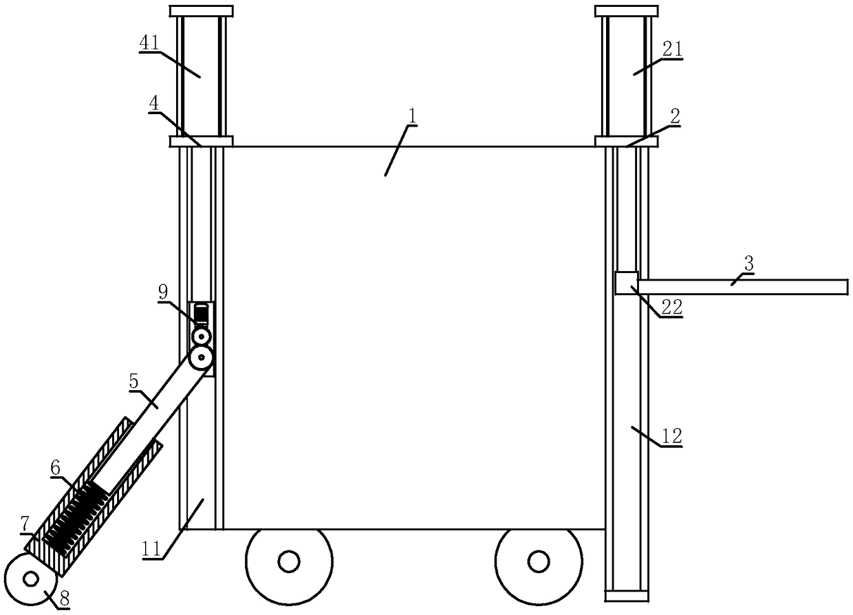
[0027] A stacker robot for preventing dumping, comprising a robot main body 1, an object lifting mechanism 2 is installed on the robot main body 1, an object supporting plate 3 is connected to the object lifting mechanism 2; an anti-tilt lifting mechanism is also connected to the robot main body 1 Mechanism 4, the anti-tilt lifting mechanism 4 is connected with a support rod 5, the other end of the support rod 5 is connected with a spring 6, and the other end of the spring 6 is connected with a support tube 7, and the spring 6 and the support rod 5 are both sleeved on the support tube 7 Inside, a roller 8 is connected to the supporting cylinder 7 .

[0028] The object-supporting lifting mechanism 2 of the present invention can drive the object-bearing plate 3 to move up and down, and then the object-bearing plate 3 can move the articles to a suitable height, which is convenient for article stacking. When the anti-tilt lifting mechanism 4 lowers the support rod 5 to a suitable ...

Embodiment 2

[0030] On the basis of Embodiment 1, the anti-tilt lifting mechanism 4 includes an anti-tilt cylinder 41, the anti-tilt cylinder 41 is installed on the robot main body 1, a sliding plate 42 is fixed on the piston rod of the anti-tilt cylinder 41, and the support rod 5 is connected to On the sliding plate 42 ; the robot main body 1 is provided with an anti-tilt chute 11 , and the sliding plate 42 is sleeved in the anti-tilt chute 11 .

[0031] The anti-tilt cylinder 41 can lift the slide plate 42, so that the support rod 5 and the support tube 7 can move to a suitable height. The sliding plate 42 always slides in the anti-tilt chute 11 to improve the stability of the sliding plate 42 during movement.

Embodiment 3

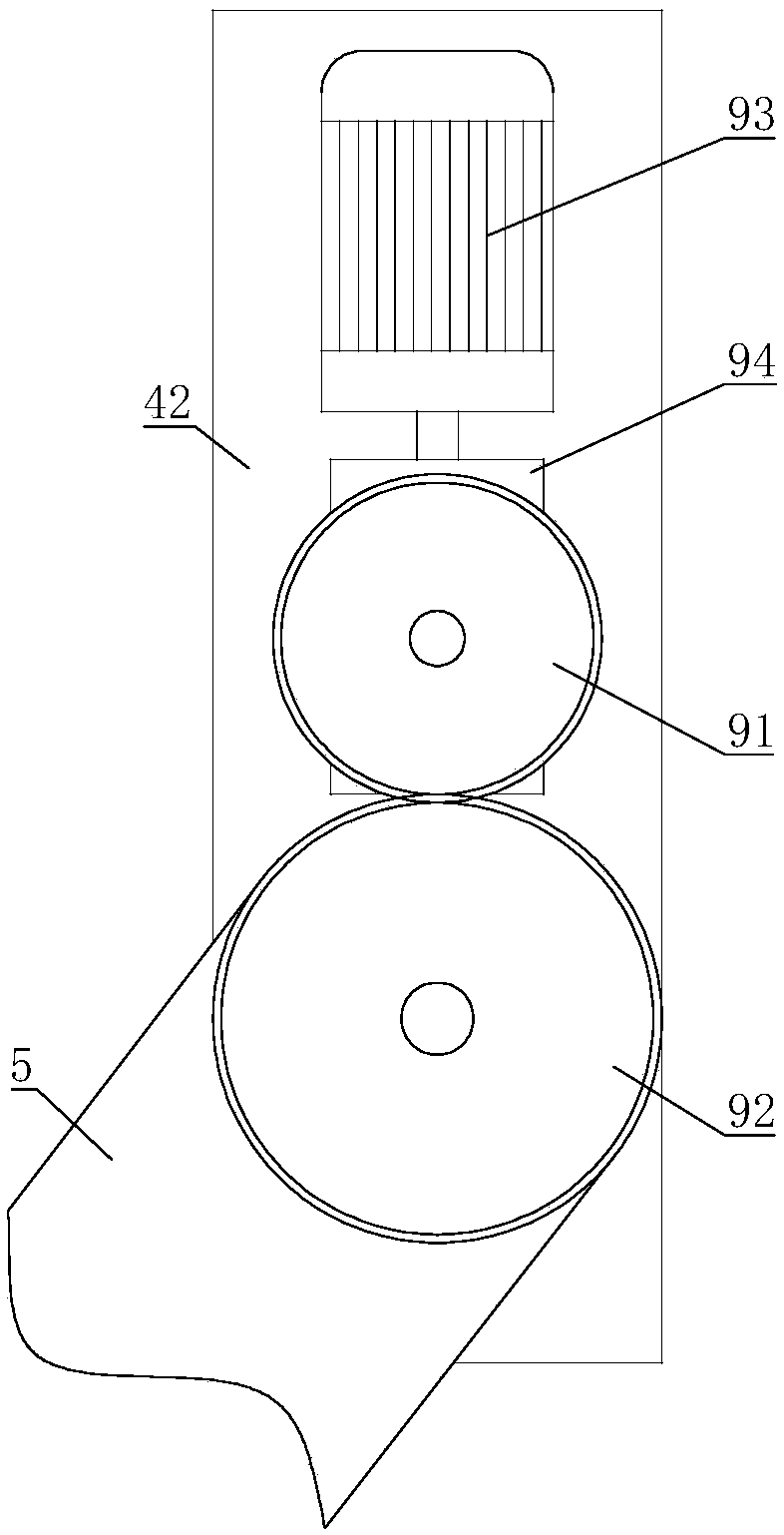
[0033] On the basis of Embodiment 1 or Embodiment 2, the support rod 5 is hinged with the sliding plate 42, the driving mechanism 9 is installed on the sliding plate 42, the output shaft of the driving mechanism 9 is connected with a driving gear 91, and the driving gear 91 is meshed with The driven gear 92 , the driven gear 92 is fixed on the supporting rod 5 , and the driven gear 92 is concentric with the rotating shaft of the supporting rod 5 .

[0034] When driving mechanism 9 drives driving gear 91 to rotate, driving gear 91 drives driven gear 92 to rotate, then support bar 5 tilts with driven gear 92, then support bar 5 and support tube 7 can be adjusted to suitable inclination angle, facilitates support tube 7 The rollers 8 on the top are stably supported to the ground, and when the robot main body 1 tilts, the support cylinder 7 and the support rod 5 have sufficient supporting force to support the robot main body 1.


PUM


Abstract

The invention relates to the field of robots, in particular to an anti-toppling stacker robot. According to the technical scheme, the anti-toppling stacker robot comprises a robot main body; a material bearing lifting mechanism is installed on the robot main body, and a material bearing plate is connected to the material bearing lifting mechanism; the robot main body is further connected with an anti-toppling lifting mechanism; one end of a supporting rod is connected to the anti-toppling lifting mechanism, the other end of the supporting rod is connected with one end of a spring, and the other end of the spring is connected with a supporting barrel; and the spring and the supporting rod are both arranged in the supporting barrel in a sleeved mode, and the supporting barrel is connected with a rolling wheel. The anti-toppling stacker robot provided by the invention can avoid toppling through the self reliable support when toppling to a certain extent, and the problem that an existing stacking robot is prone to rollover in the moving process is solved.

Description

technical field [0001] The invention relates to the field of robots, in particular to a stacker robot capable of preventing dumping. Background technique [0002] Warehouse logistics is to use self-built or leased warehouses and venues to store, store, load, unload, and distribute goods. The traditional definition of warehousing is given from the perspective of material reserves. Modern "warehousing" is not a "warehouse" in the traditional sense. "Warehouse management", but warehousing under the background of economic globalization and supply chain integration, is the warehousing in the modern logistics system. [0003] In the process of logistics warehousing and stacking, under the existing technology, most of the robotic arms stack one by one by grabbing a single item, so that in factories with a large workload, the increased labor of the robotic arm Time also increases the time of stacking, which may cause the problem of untimely stacking. Therefore, we urgently need to ...

Claims


Application Information

Patent Timeline
IPC IPC(8): B66F9/07B66F9/075B66F9/22B66F17/00
CPCB66F9/07B66F9/07559B66F9/22B66F17/00
Inventor 蒲培忠
Owner 蒲培忠
Why Eureka
Try Eureka