
Light steel frame-foamed concrete-steel wire mesh composite wall and connecting method thereof

A technology of foam concrete and connection method, which is applied in the direction of walls, anti-seismic, thermal insulation, etc., can solve the problems of unsatisfactory anti-seismic performance of the connection part, unsatisfactory anti-seismic performance and strength, poor thermal insulation performance, etc., to reduce project costs and manufacture The effect of low transportation cost and long service life

Pending Publication Date: 2019-03-08
SHENYANG JIANZHU UNIVERSITY
View PDF7 Cites 1 Cited by
  • Summary
  • Abstract
  • Description
  • Claims
  • Application Information

AI Technical Summary

Problems solved by technology

However, in the prior art, most of the light-steel frame composite walls have poor thermal insulation performance, and most of the connections between the composite walls and other composite walls and floors are connected through steel nodes, so that the seismic performance of the joints is not very ideal and cannot Meet the needs of the majority of users
[0003] Therefore, a light steel frame-foam concrete composite wall is proposed. Combining light steel frame and foam concrete can give full play to their respective advantages and achieve complementary advantages. It can not only make the wall have good strength but also have certain strength. Ductility, in order to solve the problem that the seismic performance and strength of the existing composite wall cannot be satisfied at the same time

Method used


Image

  • Light steel frame-foamed concrete-steel wire mesh composite wall and connecting method thereof
  • Light steel frame-foamed concrete-steel wire mesh composite wall and connecting method thereof
  • Light steel frame-foamed concrete-steel wire mesh composite wall and connecting method thereof

Examples


Embodiment Construction

[0028] The present invention will be further described in detail below in conjunction with the accompanying drawings and embodiments.

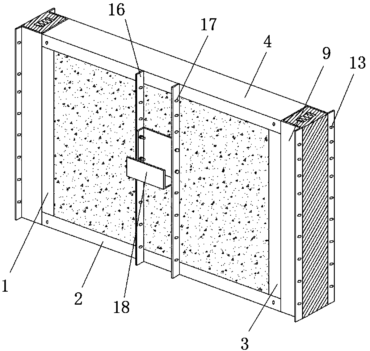
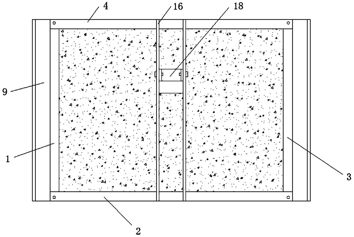
[0029] Such as Figure 1-Figure 4 As shown, a light steel frame-foam concrete-steel mesh composite wall includes four cold-formed thin-walled C-shaped channel steels, which are respectively the first channel steel 1, the second channel steel 2, the third channel steel 3 and The fourth channel steel 4, the first channel steel 1, the second channel steel 2, the third channel steel 3 and the fourth channel steel 4 are sequentially terminated and vertically intersected to form a light steel frame. The first channel steel 1, The second channel steel 2, the third channel steel 3 and the fourth channel steel 4 are welded with steel wire mesh 5 on the inner surface of the same side of the flange, and the foam concrete block 6 is symmetrically arranged in the cavity of the light steel frame, and two foam concrete Braces 7 are arranged between the bloc...


PUM


Abstract

The invention provides a light steel frame-foamed concrete-steel wire mesh composite wall and a connecting method thereof. The light steel frame-foamed concrete-steel wire mesh composite wall comprises four cold-formed thin-walled C-shaped channel steel, namely the first channel steel, the second channel steel, the third channel steel, and the fourth channel steel; the first channel steel, the second channel steel, the third channel steel and the fourth channel steelsuccessivelyintersect vertically end to end to surround a light steel frame, steel wire meshes are welded to the inner surfaces of flanges on the same sides of the first channel steel, the second channel steel, the third channel steel and the fourth channel steel, foamed concrete building blocks are symmetrically arranged in alight steel frame cavity, a brace is arranged between the two foamed concrete building blocks, a gap of the light steel frame is filled with self-compacted concrete, and connecting parts are arrangedon the surfaces of the first channel steel and the third channel steel correspondingly. The light steel frame-foamed concrete-steel wire mesh composite wall has good integrity and strength, meanwhilehas good functions of buffering and damping, and has a good vibration isolation effect when encountering high external vibration.

Description

technical field [0001] The invention belongs to the technical field of industrial and civil construction engineering, and in particular relates to a light steel frame-foam concrete-steel mesh composite wall and a connection method. Background technique [0002] The light steel frame composite wall not only has the advantages of high strength, light weight, high cost performance, and excellent fire resistance, but also when the light steel composite house is abandoned, the waste steel can be rebuilt, which can achieve resource recycling, which meets the requirements of sustainable construction. The principle of sustainable development, at the same time, the light steel frame composite wall is convenient for transfer construction, and has good structural performance. However, in the prior art, most of the light-steel frame composite walls have poor thermal insulation performance, and most of the connections between the composite walls and other composite walls and floors are c...

Claims


Application Information

Patent Timeline
Patent Type & Authority Applications(China)
IPC IPC(8): E04B2/00E04B2/74E04B1/98E04H9/02E04B1/80
CPCE04B1/80E04B2/00E04B2/7409E04H9/02
Inventor 王建超裘子铭侯微李明香马光卓
Owner SHENYANG JIANZHU UNIVERSITY
Learn More