Aircraft fuel oil conveying structure

A technology for aircraft and fuel, which is applied in the direction of turbine/propulsion fuel delivery system, fuel tank of power plant, engine components, etc. It can solve the problems of airborne equipment accessibility restrictions, connection joint leakage, limited space, etc., and achieve installation and maintenance Increased space, simple fuel system, and low cost of use

Inactive Publication Date: 2019-03-08
JIANGXI HONGDU AVIATION IND GRP
View PDF5 Cites 0 Cited by
  • Summary
  • Abstract
  • Description
  • Claims
  • Application Information

AI Technical Summary

Problems solved by technology

At present, fuel delivery is achieved by pipelines, especially for small aircraft. Due to the limited internal space of the aircraft body, the complex pipeline layout limits the accessibility of on-board equipment installation and maintenance. In addition, the vibration, impact and body deformation during the flight of the aircraft may cause loosening of the pipeline and leakage accidents at the connecting joints.

Method used


Image

  • Aircraft fuel oil conveying structure
  • Aircraft fuel oil conveying structure

Examples


Embodiment Construction

[0018] The present invention will be described in further detail below in conjunction with the accompanying drawings.

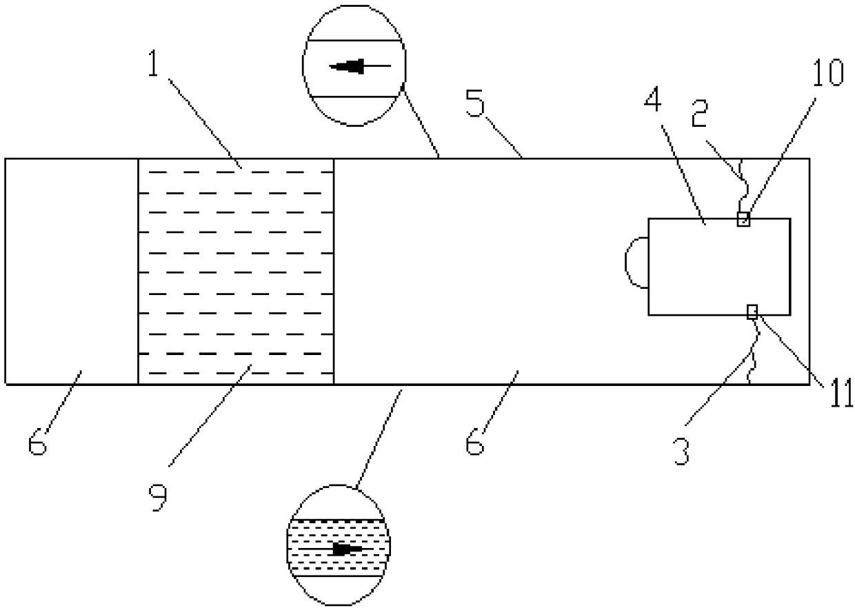
[0019] Such as figure 1 As shown, the top of the aircraft body structure 5 is provided with a first passage 7, and one end of the first passage 7 communicates with the hose I2, and the hose I2 communicates with the engine gas outlet 10; the other end of the first passage 7 communicates with the fuel tank compartment 1 connected at the top.

[0020] The bottom of the aircraft body structure 5 is provided with a second passage 8, and one end of the second passage 8 communicates with the hose 3, and the hose II 3 communicates with the engine fuel inlet 11; the other end of the second passage 8 communicates with the bottom of the fuel tank compartment 1 .

[0021] The engine pressurized gas enters the hose I2 from the engine gas outlet 10, then enters the first channel 7, and enters the top of the fuel tank compartment 1 along this channel, and then, the fuel 9...


PUM


Abstract

The invention provides an aircraft fuel oil conveying structure. A second channel (8) is formed in the bottom of an aircraft body section structure (5), one end of the second channel (8) communicateswith a hose II (3), the hose II (3) communicates with an engine fuel oil inlet (11), the other end of the second channel (8) communicates with the bottom of an oil tank cabin (1), and an air inlet isformed in the top of the oil tank cabin (1); and under the pressure of air, fuel oil (9) in the oil tank cabin enters the second channel (8) communicating with the bottom of the oil tank cabin (1), and the fuel oil (9) entering the second channel (8) enters the engine fuel oil inlet (11) along the second channel (8), so that the fuel oil (9) in the oil tank cabin (1) is conveyed to an engine (4).The fuel oil is conveyed without a pipeline, no fuel oil pipeline exists between the oil tank cabin and the engine, a large amount of space is left, so that the installation and maintenance space of airborne equipment is enlarged, the accessibility is better, and the installation is easier and more convenient.

Description

technical field [0001] The invention belongs to the technical field of aircraft fuel systems, and relates to small aircraft fuel delivery technology, in particular to an aircraft fuel delivery structure. Background technique [0002] An aircraft using a turbojet turbofan engine needs a fuel system to store fuel and deliver the fuel to the engine for the engine to work. At present, fuel delivery is achieved by pipelines, especially for small aircraft. Due to the limited internal space of the aircraft body, the complex pipeline layout limits the accessibility of on-board equipment installation and maintenance. In addition, the vibration, impact and body deformation during the flight of the aircraft may cause loosening of the pipeline and leakage accidents at the connecting joints. [0003] Therefore, the present invention provides a new fuel delivery structure to solve the problems encountered in the current aircraft fuel delivery, and has been applied in practice with good e...

Claims


Application Information

Patent Timeline
Patent Type & Authority Applications(China)
IPC IPC(8): F02C7/22B64D37/04
CPCB64D37/04F02C7/22
Inventor 周昌申阙胜才田瑞娟赵胜海张艳汪海郭祥天杨佳明李涛龙海燕王辉周伊优姚雅琳
Owner JIANGXI HONGDU AVIATION IND GRP
Why Eureka
Try Eureka