Eureka AIR delivers breakthrough ideas for toughest innovation challenges, trusted by R&D personnel around the world.

Exhausting back pressure valve

A technology of exhaust back pressure and valve body, applied in the direction of exhaust device, muffler device, engine components, etc., can solve problems such as failure of back pressure valve, and achieve the effect of prolonging service life

Pending Publication Date: 2019-03-08
南京奥联智驱电子有限公司
View PDF0 Cites 1 Cited by
  • Summary
  • Abstract
  • Description
  • Claims
  • Application Information

AI Technical Summary

Problems solved by technology

[0005] The purpose of the present invention is to provide a high temperature resistant exhaust back pressure valve to solve the problem that traditional back pressure valves work at high temperatures and are directly affected by high temperature or high temperature radiation and cause failure, prolong the life of exhaust back pressure valves, reduce user cost

Method used


Image

  • Exhausting back pressure valve
  • Exhausting back pressure valve

Examples


Embodiment 1

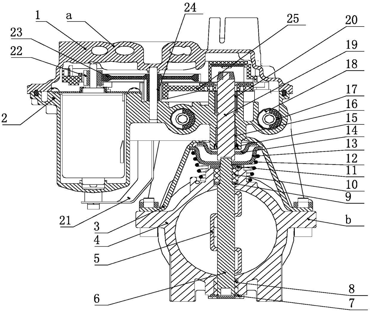
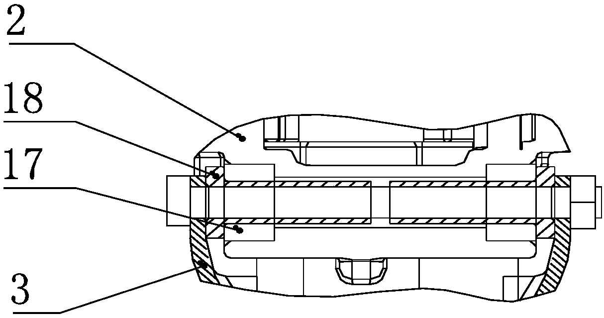
[0033] This embodiment provides an exhaust back pressure valve, which includes a motor control assembly, a valve body assembly, and a bracket connecting the motor control assembly and the valve body assembly.

[0034] Wherein, the motor control assembly includes an upper casing 1 and a lower casing 2, and an accommodation cavity is formed between the upper casing 1 and the lower casing 2, and a motor and a reducer are arranged in the accommodation cavity. In this embodiment , the motor is arranged in the cavity formed by the lower housing 2; the reducer includes a first driving gear, a first driven gear, a second driving wheel, a second driven wheel, an intermediate shaft and an output shaft .

[0035] The output shaft of the motor is coaxially fixed with a first driving gear; the first driven gear is rotatably arranged on the intermediate shaft and meshes with the first driving gear; the second driving gear The wheel is rotatably arranged on the intermediate shaft, and is fi...


PUM


Abstract

The invention discloses an exhausting back pressure valve which comprises a motor control assembly, a valve body assembly, and a support. The support is connected with the motor control assembly and the valve body assembly. The motor control assembly comprises an upper shell and a lower shell. A containing cavity is formed between the upper shell and the lower shell. A motor and a speed reducer are arranged in the containing cavity. The valve body assembly comprises an upper connecting disc, a lower connecting disc, a torsional spring, a valve body, a valve and a valve rotating shaft. An output shaft of the speed reducer is provided with the upper connecting disc. The upper connecting disc is connected with the lower connecting disc in a transmission manner. A tail gas channel whose sectional area is the same as that of a tail gas pipe is formed in the valve body. The valve is assembled on the valve rotating shaft and located in the tail gas channel of the valve body. When the exhausting back pressure valve is used, the motor control assembly and the valve body assembly are just connected partially, thus heat flowing through the tail gas channel is directly transferred to the motorcontrol assembly through the valve body assembly, and the service life of the exhausting back pressure valve is prolonged.

Description

technical field [0001] The invention relates to the technical field of diesel engine emission control devices, in particular to an exhaust back pressure valve requiring high temperature resistance in a diesel engine thermal management system. Background technique [0002] During the development and application of the National VI diesel engine, in order to meet the National VI emission regulations, basically all domestic and foreign OEMs have applied the DPF post-processor to reduce the number of particulate matter. However, one of the working methods of the DPF post-processor requires active regeneration or passive regeneration, and the particulate matter needs to be burned at high temperature. However, in some models, especially medium and light vehicles, the engine load is small and the exhaust temperature is low, resulting in difficult regeneration of the DPF after-processor and low efficiency of the SCR after-processor. [0003] The technology of increasing engine exhau...

Claims


Application Information

Patent Timeline
IPC IPC(8): F02D9/04F02D9/10F01N3/023
CPCF01N3/0235F02D9/04F02D9/10
Inventor 崔勇
Owner 南京奥联智驱电子有限公司
Why Eureka
Eureka Blog
Learn More