Fusion system for lane lines and fusion method for lane lines

A fusion method and lane line technology, applied in control/adjustment system, vehicle position/route/height control, road network navigator, etc., can solve problems such as lack of mature method for lane line fusion and affect lane change warning, etc., to achieve Great application value, good precision and accuracy, the effect of high precision and accuracy

Pending Publication Date: 2019-03-08
LIANCHUANG AUTOMOBILE ELECTRONICS
8 Cites 4 Cited by

AI-Extracted Technical Summary

Problems solved by technology

Multi-sensor target-level data fusion has also become a key technology in environmental perception. The existing simple target position and speed fusion can no longer meet the current technical requirements, and lane line fusion has become a new technical topic.
[0003] In intelligent driving, if the target and lane infor...

Abstract

The invention discloses a fusion system for lane lines based on multiple sensor data. The fusion system comprises a data receiving module, a data converting module, an own vehicle lane judging module,a target vehicle lane judging module and a target vehicle lane dividing module; the data receiving module is used for receiving target vehicle data and lane line data; the data converting module is used for converting the target vehicle data and the lane line data into the data under a preset coordinate system so as to form a lane line equation under the preset coordinate system and sequencing the lane lines formed by the lane line equation under the preset coordinate system; the own vehicle lane judging module is used for judging the lane on which the own vehicle locates according to the sequence data of the lane lines; the target vehicle lane judging module is used for substituting a target vehicle coordinate under the preset coordinate system into the lane line equation and judging which two lane lines the target vehicle locates between according to the target vehicle coordinate; and the target vehicle lane dividing module is used for judging the number of the lane on which the target vehicle locates according to the number of the lane on which the own vehicle locates. The invention also discloses a fusion method for lane lines. According to the invention, lane line dividing can be realized; diversity of surrounding information acquired by intelligent driving can be increased; and higher accuracy of lane line detection can be provided.

Application Domain

Technology Topic

Image

  • Fusion system for lane lines and fusion method for lane lines
  • Fusion system for lane lines and fusion method for lane lines
  • Fusion system for lane lines and fusion method for lane lines

Examples

  • Experimental program(1)

Example Embodiment

[0056] An embodiment of the lane line fusion system provided by the present invention, based on multi-sensor target-level data, includes: a data receiving module, a data conversion module, a lane judging module and a target lane line dividing module;
[0057] The data receiving module includes at least the position and speed of the target vehicle monitored by the radar, and the lane line equation coefficient of the lane line detection system.
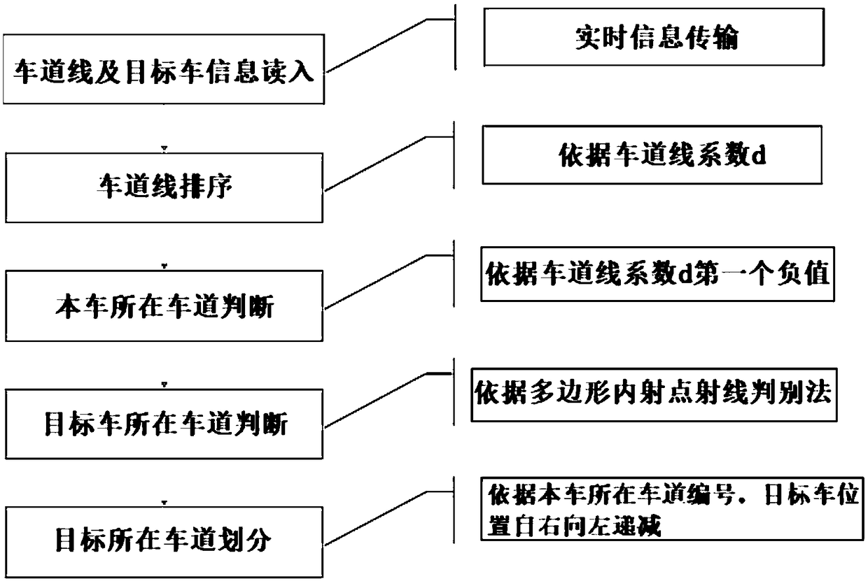
[0058] a data conversion module, which converts the target vehicle data and lane line data into data under a preset coordinate system, forms a lane line equation under the preset coordinate system, and sorts the lane lines formed by the lane line equation under the preset coordinate system;
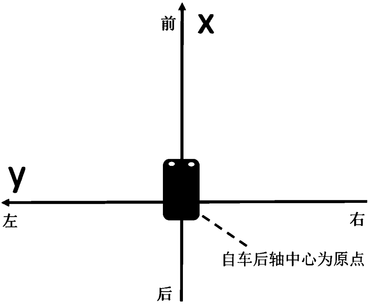
[0059] refer to figure 1 As shown, the preset coordinate system is a coordinate system with the center of the rear axle of the vehicle as the origin, the axis of the vehicle as the x-axis, the front of the vehicle as positive, the direction of the rear axis of the vehicle as the y-axis, and the left side as the positive coordinate system . The lane line equation is as follows;
[0060] y=ax 3 +bx2 +cx+d, where x and y are the coordinates under the vehicle coordinate system, and a, b, c, and d are the lane line equation coefficients sent by the lane line detection system.
[0061] The sorting rules are as follows: the lane lines are sorted from left to right in the coordinate system of the vehicle, and the lane lines are sorted according to the size of the coefficient d of the lane line equation.
[0062] The lane judgment module of the vehicle determines the lane where the vehicle is located according to the lane line sorting data; the following methods are used to determine the lane where the vehicle is located;
[0063] After sorting through the lane lines of the vehicle's coordinates, the first negative coefficient d is the lane line on the right side of the vehicle, and one of the lane lines on the right side is the lane line on the left side of the vehicle.
[0064] The target vehicle lane line judgment module brings the coordinates of the target vehicle in the preset coordinate system into the lane line equation, and judges which two lane lines the target vehicle is located between according to the target vehicle coordinates; and judges which two lane lines the target vehicle is located on. The following methods are used between: Bring the coordinates of the target car into the lane line equation, and judge the lane where the target car is located according to the polygon interior point ray discrimination method.
[0065] The target vehicle lane division module determines the lane number of the target vehicle according to the lane number of the own vehicle.
[0066] The lane division rules of the target vehicle are as follows. According to the lane number of the own vehicle, the lane number of the target vehicle is determined. Calculate the lane where the point is located according to the size relationship between y (target) and Y (lane line calculation result): Sort the x-coordinates of the target vehicle (x, y) according to the lane lines, and bring them into the lane line equation from left to right to find get Y. Comparing the relationship between y and Y, y>Y is recorded as 1, that is, the target is on the left side of the currently calculated lane line; y
[0067] The present invention provides a lane line fusion method, which is based on multi-sensor target-level data and includes the following steps:
[0068] 1) Receive the target car data and lane line data, assuming that 4 lane line equations and the position of the target car are read;
[0069] 2) Convert the target vehicle data and lane line data into data under the preset coordinate system, and form the lane line equation under the preset coordinate system; the preset coordinate system is, taking the center of the rear axle of the vehicle as the origin, and The vehicle axis is the x-axis, the front of the vehicle is positive, the rear axis of the vehicle is the y-axis, and the left side is the positive coordinate system; the lane line equation is as follows;
[0070] y=ax 3 +bx 2 +cx+d, where x and y are the coordinates under the vehicle coordinate system, and a, b, c, and d are the lane line equation coefficients sent by the lane line detection system.
[0071] 3) Sort the lane lines formed by the lane line equation in the preset coordinate system, the lane lines are sorted from left to right in the own vehicle coordinate system, and the lane lines are sorted according to the size of the coefficient d of the lane line equation, assuming from left to right sort as image 3 shown in A;
[0072] 4) Determine the lane where the vehicle is located according to the lane line sorting data. After sorting through the coordinate lane lines of the vehicle, the first negative coefficient d is the right lane line of the vehicle, and one of the right lane lines is the left side of the vehicle. lane line.
[0073] like image 3 The lane where the self-vehicle is located is number 0, the first lane on the left is 1, and the first lane on the right is -1.
[0074] 5) Bring the coordinates of the target vehicle in the preset coordinate system into the lane line equation, and determine the lane where the target point is located according to the polygon interior point ray discrimination method. Determine whether a point is an interior point of a polygon, and draw a ray through the polygon if there is an odd number of lines on the left and right, it is an interior point, otherwise it is not. The area contained within the two lane lines is assumed to be a very long polygon along the x-axis.
[0075] 6) According to the lane number of the vehicle, determine the lane number of the target vehicle. Calculate the lane where the point is located according to the size relationship between y (target) and Y (lane line calculation result): Sort the x-coordinates of the target vehicle (x, y) according to the lane lines, and bring them into the lane line equation from left to right to find get Y. Comparing the relationship between y and Y, y>Y is recorded as 1, that is, the target is on the left side of the currently calculated lane line; y
[0076] The present invention has been described in detail above through specific embodiments and examples, but these are not intended to limit the present invention. Without departing from the principles of the present invention, those skilled in the art can also make many modifications and improvements, which should also be regarded as the protection scope of the present invention.

PUM

no PUM

Description & Claims & Application Information

We can also present the details of the Description, Claims and Application information to help users get a comprehensive understanding of the technical details of the patent, such as background art, summary of invention, brief description of drawings, description of embodiments, and other original content. On the other hand, users can also determine the specific scope of protection of the technology through the list of claims; as well as understand the changes in the life cycle of the technology with the presentation of the patent timeline. Login to view more.

Similar technology patents

Classification and recommendation of technical efficacy words

  • Improve precision and accuracy
  • Increase diversity

Information recommendation system and information recommendation method

InactiveCN106327227AIncrease diversityOptimize the recommendation functionMarketingRecommender systemThe Internet
Owner:航天信息软件技术有限公司
Why Eureka
Try Eureka