
Self-testing device and method of silicon-based display device and silicon-based display device

A display device and self-testing technology, which is applied in the testing of machines/structural components, measuring devices, optical instruments, etc., can solve problems such as inflow of defective products, ineffective production, waste of raw materials, etc., and achieve feasible technical solutions and broad application prospects , the effect of improving production efficiency

Inactive Publication Date: 2019-03-08
CHENGDU JINGSHA TECH
View PDF4 Cites 0 Cited by
  • Summary
  • Abstract
  • Description
  • Claims
  • Application Information

AI Technical Summary

Problems solved by technology

Regardless of the type of micro-display technology, it is prone to uneven brightness or black spots, bright spots and other quality defects during the production process. Products with such serious defects cannot be provided to customers as qualified products.
However, in the current production process of silicon-based display devices, it is necessary to connect external test signal generation equipment, test control devices and other fixtures after the final manufacturing processes such as device cover glass attachment and FPC (flexible circuit board) binding are completed. The display screen is tested for electrical signals to find defective products, such as figure 1
This not only requires the configuration of additional testing equipment, the production efficiency is low, but also because defective products cannot be found as early as possible in the previous process of the production process, resulting in defective products flowing into the subsequent process, which not only wastes the raw materials of the subsequent process, but also causes the latter process to be invalid. Production

Method used


Image

  • Self-testing device and method of silicon-based display device and silicon-based display device
  • Self-testing device and method of silicon-based display device and silicon-based display device
  • Self-testing device and method of silicon-based display device and silicon-based display device

Examples


Embodiment Construction

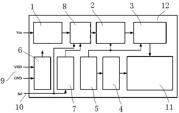
[0028] In order to make the purpose, technical solutions and advantages of the present invention clearer, the technical solutions in the embodiments of the present invention will be clearly and completely described below in conjunction with the accompanying drawings in the embodiments of the present invention. Obviously, the described embodiments are only It is a part of embodiments of the present invention, but not all embodiments. Based on the embodiments of the present invention, all other embodiments obtained by persons of ordinary skill in the art without making creative efforts belong to the protection scope of the present invention. In the case of no conflict, the embodiments and the features in the embodiments of the present invention can be combined arbitrarily with each other. Also, although a logical order is shown in the flowcharts, in some cases the steps shown or described may be performed in an order different from that shown or described herein.

[0029] see ...


PUM


Abstract

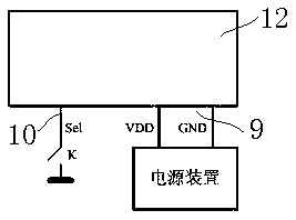
The invention discloses a self-testing device of a silicon-based display device. The device comprises a test power input port, an external control pin, a signal generator module and a signal selectionmodule, wherein the external control pin is arranged on the silicon-based display device and used for receiving an external self-testing control signal during self-testing; the signal generator module is arranged in a driving circuit of the silicon-based display device and is used for generating a test image signal relative to the self-testing control signal when the self-testing control signal received by the external control pin is received; the signal selection module is arranged in the driving circuit of the silicon-based display device and used for connecting a transmission path for transmitting the test image signal between the signal generator module and an image processing module when receiving the self-testing control signal received by the external control pin. The invention also discloses a self-testing method and the silicon-based display device. The self-testing device does not need to be externally connected with a test signal generation device, a test control device andthe like, so that the production efficiency is improved, defective products are screened out through a photoelectric performance test before all process procedures of the silicon-based display deviceare completed, and the defective products can be prevented from flowing into later procedures.

Description

technical field [0001] The invention relates to the field of display technology, in particular to a self-test device, a self-test method and a silicon-based display device of LCOS, Micro-OLED, Micro-LED and other silicon-based display devices. Background technique [0002] Display devices based on different display technologies can be divided into large-size displays for TVs, medium-size displays for smartphones, tablet computers, and other products according to screen size, and for helmet-mounted displays, VR (virtual reality), etc. Micro-displays for near-eye display; according to the different backplanes used in light-emitting devices, they can be divided into conventional display screens with glass backplanes and silicon-based display devices with integrated circuit wafers as backplanes. Silicon-based display devices mainly include LCOS (liquid crystal on silicon), Micro-OLED (micro-display organic light-emitting diode), Micro-LED (micro-display light-emitting diode) and...

Claims


Application Information

Patent Timeline
IPC IPC(8): G01M11/02
CPCG01M11/00
Inventor 田国军黎守新陈珉
Owner CHENGDU JINGSHA TECH
Learn More