Shading mechanism of test lamp box

A technology for testing light boxes and shading cloths, applied in shading, optics, nonlinear optics, etc., can solve problems such as complex structure of shading mechanism, influence on test results, troublesome operation, etc., and achieve the effect of simple structure, improved precision, and convenient operation

Pending Publication Date: 2019-03-08
苏州市琳珂照明科技有限公司
View PDF0 Cites 0 Cited by
  • Summary
  • Abstract
  • Description
  • Claims
  • Application Information

AI Technical Summary

Problems solved by technology

[0003] When large-sized test equipment tests small-sized LCD panels, the part of the light-emitting area in the test light box that interferes with the optical detection instrument needs to be blocked. At present, a light-shielding mechanism composed of a light-shielding cloth, a slide rail and a screw rod is generally used in actual production. Shading, this method shields the light box from three directions, but this kind of shading method is prone to light leakage, which affects the test results, and the structure of the shading mechanism is complex and the operation is troublesome

Method used


Image

  • Shading mechanism of test lamp box
  • Shading mechanism of test lamp box
  • Shading mechanism of test lamp box

Examples


Embodiment 1

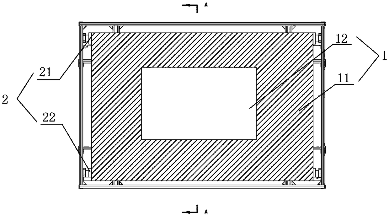
[0026] Test the light box's shading mechanism, such as Figures 1 to 3 As shown, it includes a shade cloth 1, a rolling device 2 and a lifting device 4.

[0027] The shading cloth 1 is provided with a shading area 11 and more than one light-transmitting area 12. The shading cloth 1 is made of a tensile and opaque material. The opaque part is the shading area 11.

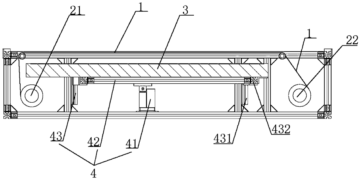
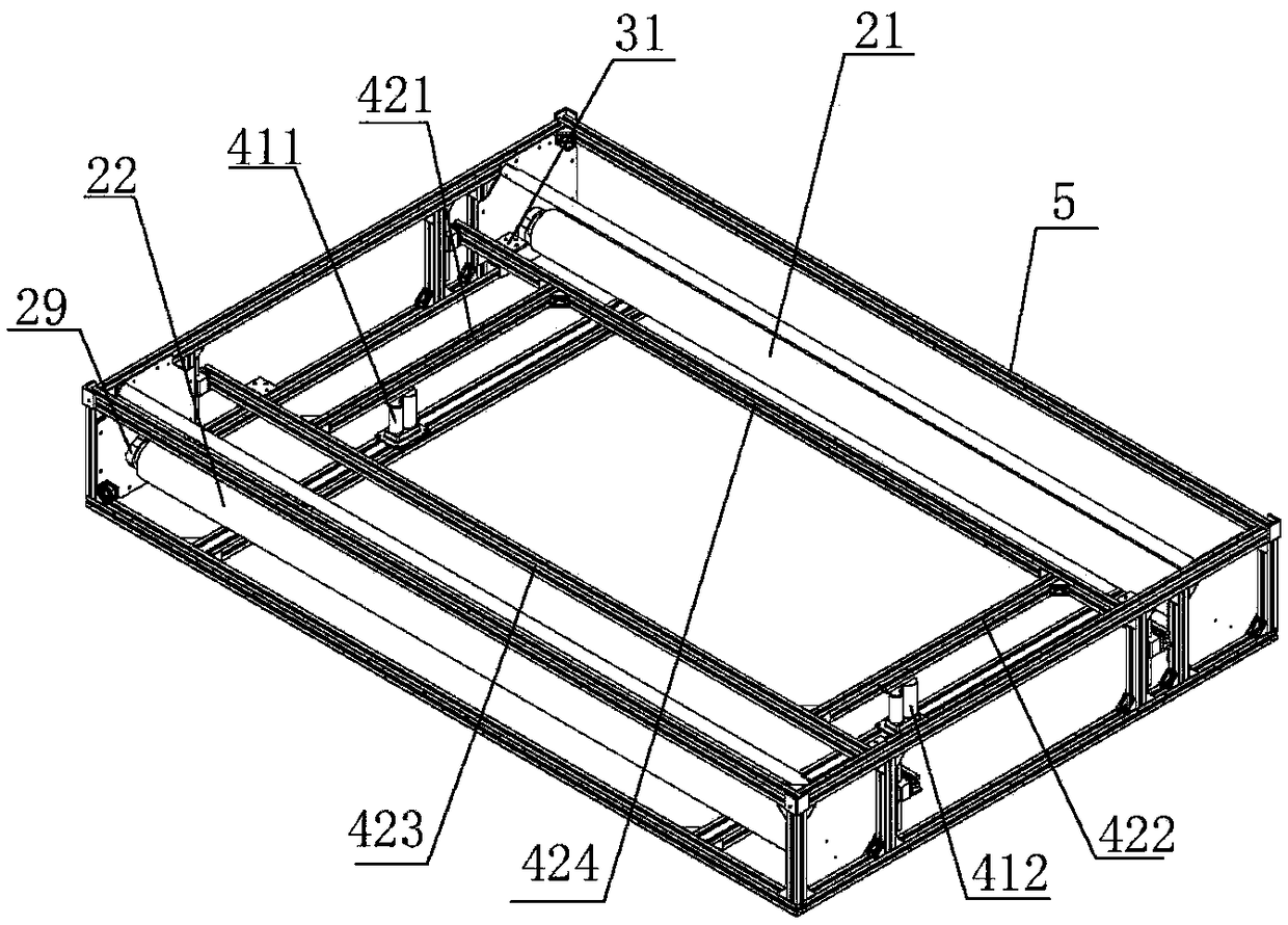
[0028] The rolling device 2 includes a first roller 21 and a second roller 22, the first roller 21 and the second roller 22 are respectively arranged on both sides inside the test lamp box, and are fixed on the test lamp box frame 5 by a roller connector 29 Above, the first roller 21 and the second roller 22 are arranged in parallel.

[0029] Both ends of the shade cloth 1 are respectively fixed on the first roller 21 and the second roller 22 , and the shade cloth is wound on the first roller 21 and the second roller 22 .

[0030] Lifting device 4 is arranged on the below of shading cloth 1, comprises driving elem...

Embodiment 2

[0037] A shading mechanism for testing light boxes such as Figure 4 As shown, the shading mechanism includes a shading cloth 1 and a rolling device. At the same time, a light source unit 3 is arranged in the test light box. The light-transmitting area 12 is hollowed out on the light-shielding cloth 1 during production, and the surrounding opaque parts are the light-shielding areas 11, and each light-transmitting area 12 corresponds to a product size of a type.

[0038] The rolling device 2 includes a first roller 21 and a second roller 22, the first roller 21 and the second roller 22 are respectively arranged on both sides inside the test lamp box, and are fixed on the test lamp box frame 5 by a roller connector 29 Above, the first roller 21 and the second roller 22 are arranged in parallel, the shading cloth 1 is connected end to end, and the side is ring-shaped, and is wound on the first roller 21 and the second roller 22. At this time, the light source unit 3 is placed in...

Embodiment 3

[0041] A shading mechanism for testing light boxes such as Figures 5 to 6 As shown, the shading mechanism includes a shading cloth 1 and a rolling device 2. At the same time, a light source unit 3 is arranged in the test light box. Made of drawn, opaque material, the light-transmitting area 12 is hollowed out on the light-shielding cloth 1 during production, and the surrounding opaque parts are the light-shielding areas 11, and each light-transmitting area 12 corresponds to a product size of a model .

[0042] The rolling device 2 comprises a first rack 23, a second rack 24, a first gear 25, a second gear 26, a third gear 27 and a fourth gear 28, and the first rack 23 and the second rack 24 are respectively arranged on The back of the shading cloth 1 is fixedly connected to the two sides of the shading cloth 1, the first rack 23 and the second rack 24 are arranged in parallel, the first gear 25 and the third gear 27 mesh with the first rack 23, and the second gear 26 and th...


PUM


Abstract

The invention discloses a shading mechanism of a test lamp box. The shading mechanism mainly includes shading cloth and a rolling device. The shading cloth is provided with a shading region and more than one light-pervious region; the rolling device is used for winding the shading cloth and driving the same to roll so that the light-pervious regions are switched. The shading mechanism disclosed herein has the advantages that when the test lamp box is used to detect different models of products, the rolling device drives the shading cloth inside a lamp box to switch the different light-perviousregions so that the various models of products can be detected on the same test lamp box; the shading mechanism is simple in structure, easy to operate and low in time cost and is effective in decreasing the chances for light leaking during detection and improving accuracy of detection results.

Description

technical field [0001] The invention relates to the field of test equipment, in particular to a light shielding mechanism for a test light box. Background technique [0002] With the development of the economy and the improvement of people's living standards, various types of liquid crystal application products play an increasingly important role in the production of the national economy and people's social life. Liquid crystal application products are increasingly diversified and popularized. In the process, in order to improve the versatility and cost performance of the product, it is necessary to test the optical characteristics of the liquid crystal panel. During the test, a light-emitting light box is usually used to replace the backlight module in the liquid crystal display. Due to the increasing size of liquid crystal panels, in actual production, it is often necessary to test a variety of liquid crystal panel models with one testing device. [0003] When large-sized...

Claims


Application Information

Patent Timeline
Patent Type & Authority Applications(China)
IPC IPC(8): G02F1/13
CPCF21V1/00F21V1/16F21V14/08G02F1/1309
Inventor 鲁周波
Owner 苏州市琳珂照明科技有限公司
Why Eureka
Try Eureka