Electromagnetic system of clapper type magnetic latching relay, and assembly method thereof

A technology of magnetic latching relays and electromagnetic systems, applied in the direction of electromagnetic relays, electromagnetic relay details, relays, etc., can solve the problem that the operation effect of electromagnetic system relays is not reliable, the connection mode of the impact-resistant structure is not prominent, and the electromagnetic system is not suitable for various Specific issues such as low power consumption, strong anti-vibration ability, and high reliability are achieved.

Pending Publication Date: 2019-03-08
浙江凡华电子股份有限公司
View PDF1 Cites 3 Cited by
  • Summary
  • Abstract
  • Description
  • Claims
  • Application Information

AI Technical Summary

Problems solved by technology

[0004] The above scheme solves the problem that the existing magnetic latching relay electromagnetic system is not suitable for various specific relay products and the magnetic attraction is not easy to adjust to a certain extent. However, this scheme still has many s...

Method used


Image

  • Electromagnetic system of clapper type magnetic latching relay, and assembly method thereof
  • Electromagnetic system of clapper type magnetic latching relay, and assembly method thereof
  • Electromagnetic system of clapper type magnetic latching relay, and assembly method thereof

Examples


Embodiment Construction

[0032] The present invention will be described in further detail below in conjunction with the accompanying drawings and specific embodiments.

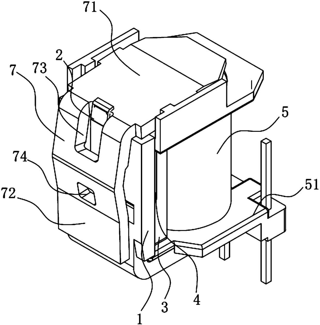
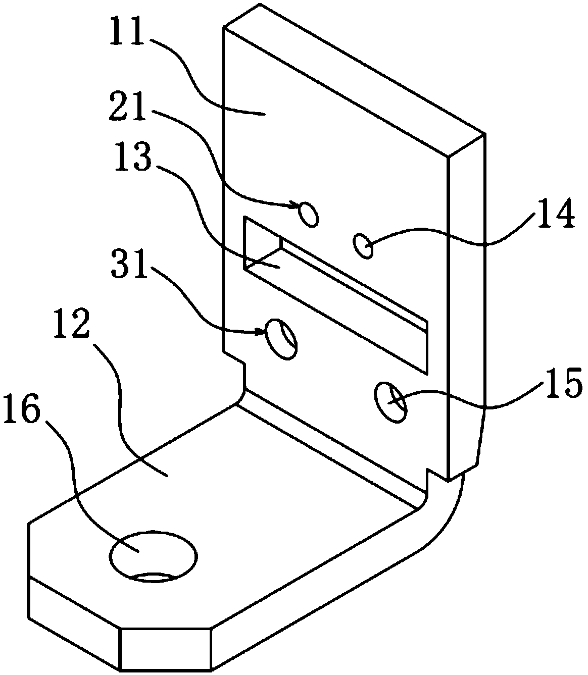
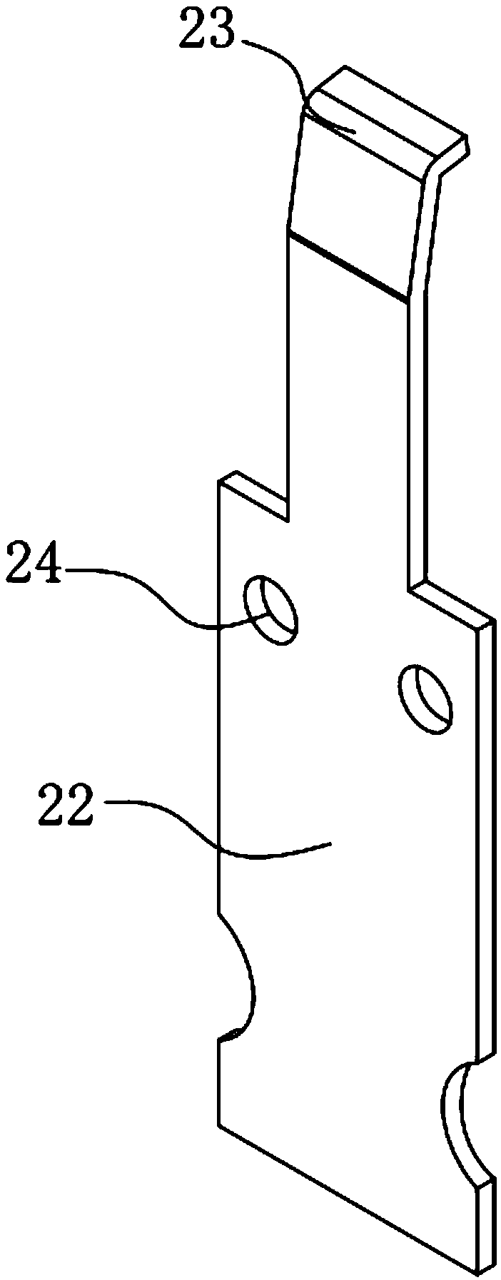
[0033] Such as Figure 1-7 As shown, the clapping-type magnetic latching relay electromagnetic system includes an electromagnetic part and a yoke assembly. The yoke assembly includes an L-shaped yoke 1 having a vertical portion 11 and a horizontal portion 12. The vertical portion 11 of the yoke 1 The outer side is provided with a compression spring 2, the inner side is provided with a magnetic conduction block 3, and the vertical part 11 of the yoke 1 is provided with a rectangular hole 13 which can connect the compression spring 2 and the magnetic conduction block 3, and the compression spring 2 and the magnetic conduction block The blocks 3 are all connected to the yoke 1 through the first riveting structure, and a magnetic steel 4 is provided between the vertical part 11 of the yoke 1 and the magnetic block 3, and the electromagnet...


PUM


Abstract

The invention relates to an electromagnetic system of a clapper type magnetic latching relay for solving the problem that the existing electromagnetic system of the magnetic latching relay is unsteadyin structure, unreliable in operation and difficult to adjust magnetic attraction force. The electromagnetic system of the clapper type magnetic latching relay comprises an electromagnetic part and ayoke component; the yoke component comprises a yoke; a pressure spring is arranged outside the vertical part of the yoke; a magnetic conduction block is arranged at the inner side; a rectangular holeis arranged on the vertical part of the yoke; furthermore, both the pressure spring and the magnetic conduction block are connected with the yoke; magnetic steel is arranged between the vertical partof the yoke and the magnetic conduction block; the electromagnetic part comprises a coil; an iron core is arranged in the coil in a penetrating manner; furthermore, the upper end of the iron core extends to be above the coil; the vertical part of the yoke is positioned at one side of the coil; the horizontal part of the yoke is connected with the iron core; an armature is arranged at one side ofthe yoke away from the coil; the straight part of the armature is connected with the upper end of the iron core; and a push card square hole is on the bended part of the armature. The electromagneticsystem of the clapper type magnetic latching relay has the advantages of being simple and steady in structure, reliable in operation, easy to adjust the magnetic attraction force and the like.

Description

technical field [0001] The invention belongs to the technical field of circuit control, and in particular relates to an electromagnetic system of a snap-in type magnetic latching relay and an assembly method thereof. Background technique [0002] Magnetic latching relay is an electronic control device, which belongs to the polarization relay in the category of electromagnetic relay, and plays the role of automatic adjustment, safety protection, conversion circuit, etc. in the circuit. The magnetic latching relay is a new type of relay developed in recent years. Its normally closed or normally open state depends on the action of the magnet. According to relevant information, the contact switching current of the magnetic latching relay on the market can reach up to 150A, and the control coil voltage is divided into DC9V, DC12V, etc., which can generally reach 10,000 times of electrical life, 1,000,000 times of mechanical life, and contact pressure drop <100mV. Therefore, ...

Claims


Application Information

Patent Timeline
IPC IPC(8): H01H51/01H01H50/16H01H50/04H01H49/00
CPCH01H51/01H01H49/00H01H50/042H01H50/16
Inventor 谢文骏何炎丰
Owner 浙江凡华电子股份有限公司
Why Eureka
Try Eureka