Terminal module, socket and terminal

A terminal module and terminal group technology, which is applied to the base/housing, contact parts, electrical components, etc., can solve the problems of large waterproof structure, low utilization rate of terminal structure, and high waterproof cost of terminal modules. The effect of improving the utilization rate of the structure and guaranteeing the waterproof effect

Active Publication Date: 2019-03-08
NUBIA TECHNOLOGY CO LTD
View PDF7 Cites 1 Cited by
  • Summary
  • Abstract
  • Description
  • Claims
  • Application Information

AI Technical Summary

Problems solved by technology

[0004] The technical problem to be solved by the present invention is that the waterproof cost of the existing terminal module is too high, and at the same time, the size of the waterpro

Method used


Image

  • Terminal module, socket and terminal
  • Terminal module, socket and terminal
  • Terminal module, socket and terminal

Examples


no. 1 example

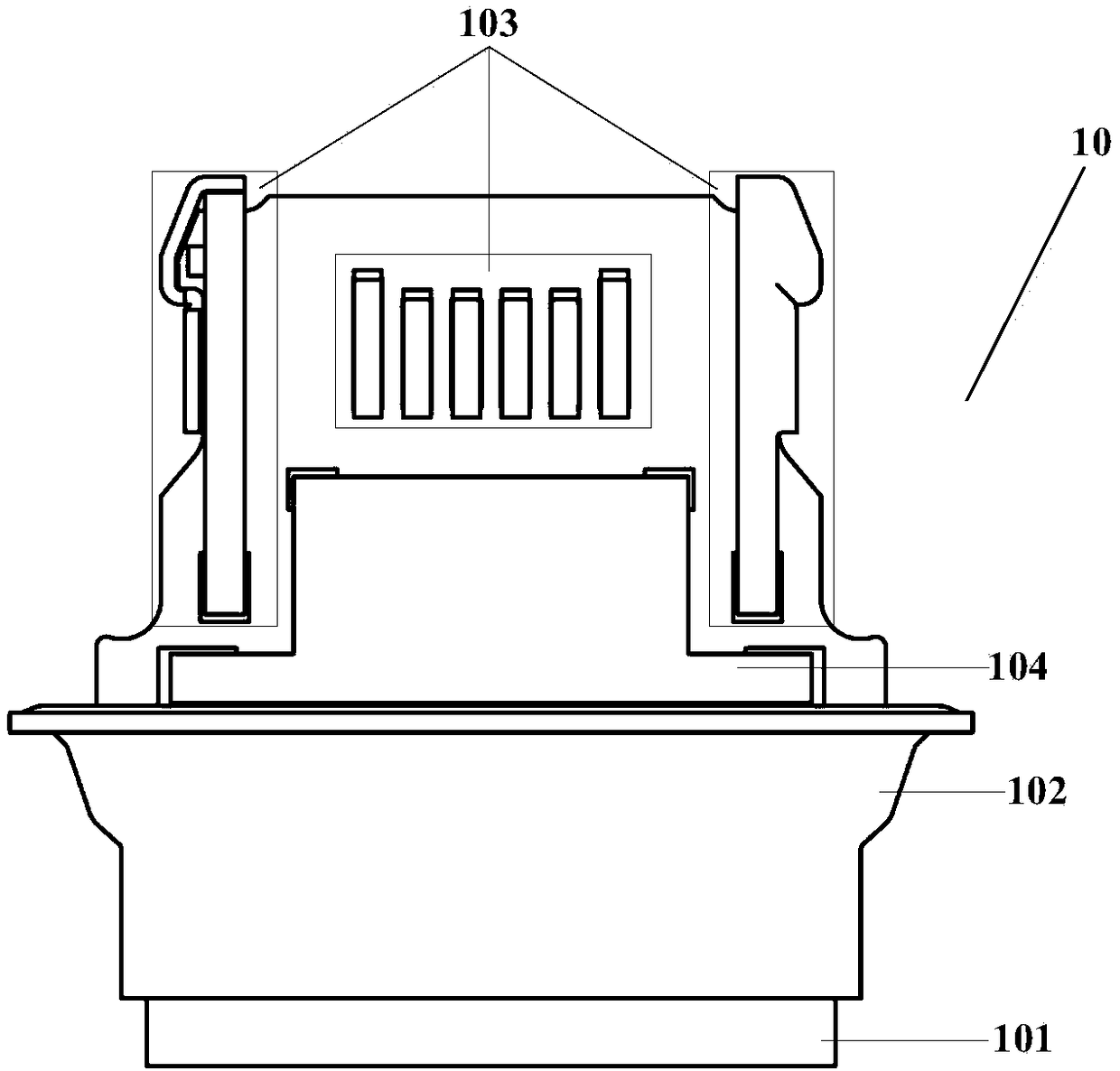
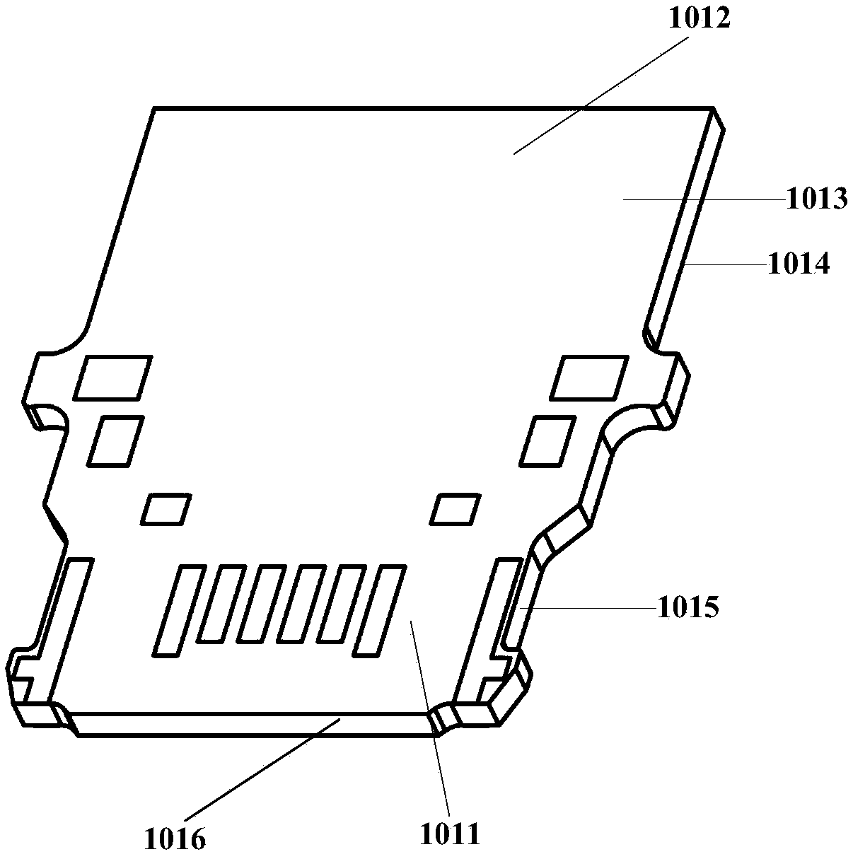
[0051] In order to solve the problem that the waterproof cost of the existing terminal module is too high, and the size of the waterproof structure is large, resulting in a low utilization rate of the terminal structure, this embodiment provides a terminal module, see figure 1 As shown, the terminal module 10 includes a printed circuit board (Printed circuit board, PCB) 101 , a waterproof member 102 , terminals 103 and an electromagnetic interference sheet (Electromagnetic Interference, EMI) 104 . In order to better understand the present invention, the positional relationship of the printed circuit board 101 set forth in the present invention is firstly described here, see figure 2 As shown, 1011 is called one end of the printed circuit board, 1012 is the other end of the printed circuit board, obviously, 1011 and 1012 are opposite ends, 1013 is the upper end of the printed circuit board, 1014 is the lower end of the printed circuit board, 1015 is the side of the printed cir...

no. 2 example

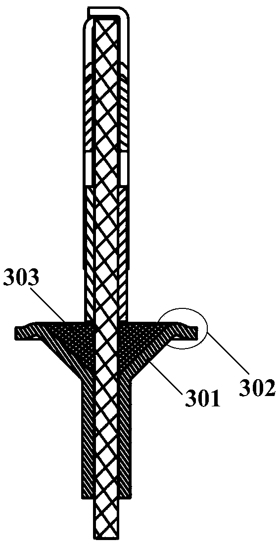
[0075] In order to better understand the present invention, this embodiment is described with a specific terminal module, see Figure 10 As shown, the terminal module 100 includes a printed circuit board 1001, a waterproof member 1002, a terminal 1003 and an electromagnetic interference sheet 1004, and the waterproof member 1002, the terminal 1003 and the electromagnetic interference sheet 1004 are fixed on the printed circuit board 1001 by patch welding; Wherein, the waterproof member 1002 is arranged on one end of the printed circuit board 1001, and the waterproof member 1002 covers one end of the printed circuit board 1001, specifically, the waterproof member has a “Y” structure; the terminal 1003 is arranged on the other end of the printed circuit board 1001 , the other end is the end opposite to the waterproof member 1002. Specifically, the terminal 1003 includes an outer terminal group, wherein the outer terminal group includes an outer upper terminal group and an outer l...


PUM


Abstract

The invention discloses a terminal module, a socket and a terminal. The terminal module comprises a printed circuit board, a waterproof piece, a terminal and electromagnetic interference pieces, wherein the waterproof piece is arranged at one end of the printed circuit board; the waterproof piece is coated on one end of the printed circuit board; the terminal is arranged at the other end of the printed circuit board, and the other end is the end opposite to the waterproof piece; and the electromagnetic interference pieces are arranged on the surfaces of the upper end and the lower end of the printed circuit board respectively. The problem that the utilization rate of the terminal structure is low caused by the facts that the waterproof cost of an existing terminal module is too high and simultaneously the dimensions of a waterproof structure are relatively large is solved. The invention also discloses the socket and the terminal. Through the implementation of the scheme, the waterproofcost is saved, and simultaneously, the utilization rate of the terminal structure is improved.

Description

technical field [0001] The invention relates to the field of sockets, and more specifically, to a terminal module, a socket and a terminal. Background technique [0002] USB TYPE C is a new type of interface that can be expanded into three interfaces of power supply / USB transmission / VGA or HDMI. Through an adapter, it can also be compatible with USB3.O, USB2.0 and other previous generation interfaces. Input and output interfaces for data transmission, connection with external devices, and power supply for each device. [0003] The existing USB TYPE C socket structure generally includes a terminal module and a housing. If waterproofing is to be achieved, two steps are usually required, one of which is to realize waterproofing between the terminal module and the USB housing, and the other is to realize waterproofing between the terminal module and the USB housing. The waterproof design of the USB shell and the terminal casing leads to high cost, and the size of the two waterp...

Claims


Application Information

Patent Timeline
IPC IPC(8): H01R13/52H01R13/502H01R13/66H01R13/6581H01R13/02
CPCH01R13/02H01R13/502H01R13/5202H01R13/6581H01R13/665
Inventor 张大玉
Owner NUBIA TECHNOLOGY CO LTD
Why Eureka
Try Eureka