Wiring terminal storage clip and wiring clamp with storage clip
What is AI technical title?
AI technical title is built by Patsnap AI team. It summarizes the technical point description of the patent document.
A technology of wiring terminals and wire clamps, applied in the field of wire clamps, can solve the problems of forgetting to carry, inconvenient, and small in size.
Pending Publication Date: 2019-03-08
黄勐
View PDF0 Cites 0 Cited by
Summary
Abstract
Description
Claims
Application Information
AI Technical Summary
This helps you quickly interpret patents by identifying the three key elements:
Problems solved by technology
Method used
Benefits of technology
Problems solved by technology
The original parts such as wiring subs are small and easy to lose or forget to carry, which makes it impossible to carry out wiring operations
And the wiring is more cumbersome
[0003] In particular, if the connectors or crystal plugs are properly placed with the core wires of telecommunication cables, they may loosen and fall off when crimping with tools, which will cause inconvenience
Method used
Image
Click on the blue label to locate the original text in one second.
Reading with bidirectional positioning of images and text.
Examples
Embodiment 1
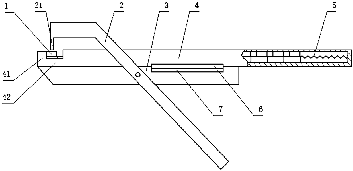
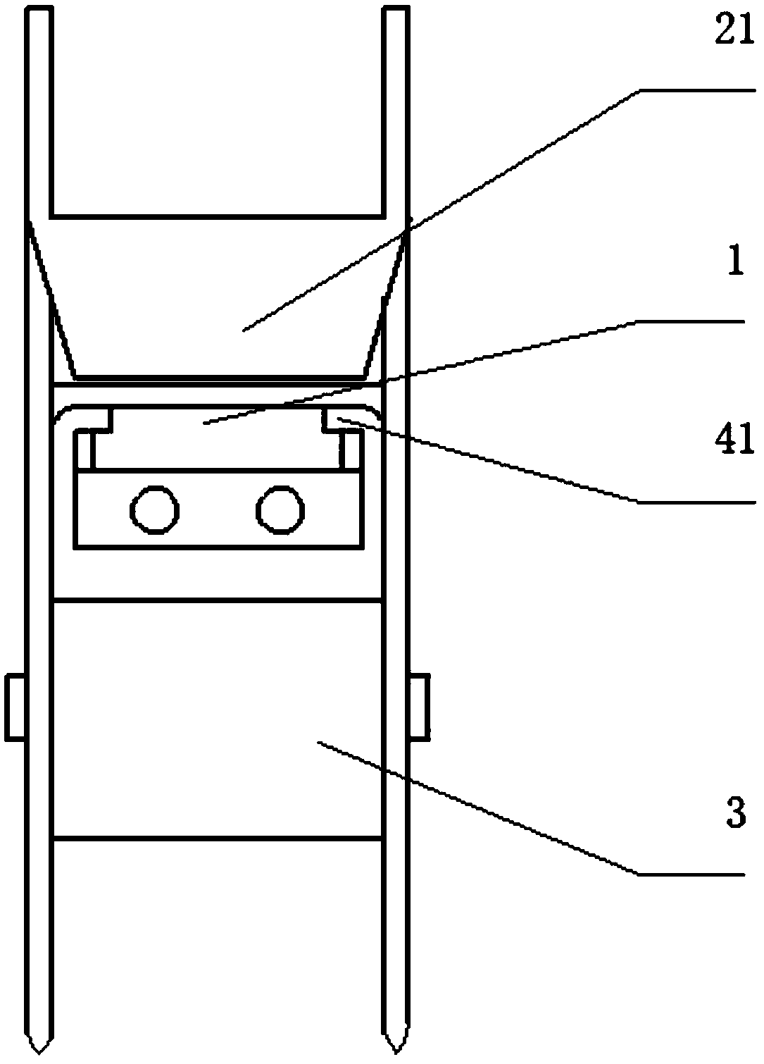
[0037] Such as figure 1 As shown, a wiring pliers used for the terminal 1, the terminal 1 is a 3M brand terminal, such as the K2 model. The storage clip 4 is connected to the body of the second pliers handle 3 . In fact, the two can be fixedly connected.
[0038] refer to figure 2 , The storage clip 4 includes a top wall, a bottom wall and side walls connecting the top wall and the bottom wall, and a long storage space is enclosed inside. figure 1 The left section is the jaw section 42, and the jaw section 42 removes the top wall as the jaw. The length of the jaws is sufficient for the terminal 1 to be pressed into the storage space from the outside.
[0039] The right section is a storage section, in which a spring 5 is arranged, and the terminal 1 that is pressed into the storage section successively squeezes the spring 5 continuously, and is pushed into the jaw section 42 by the thrust of the spring 5 at the same time. A stopper 41 is provided at the left end of the ja...
Embodiment 2
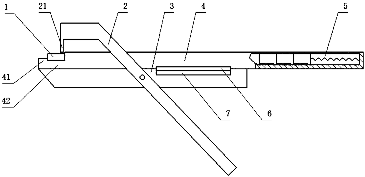
[0046] Such as image 3 , Figure 4 As shown, the connector 1 is a crystal head used for a telephone line or a network cable. The overall dimension does not change when it is pressed.
[0047] The connectors 1 are arranged sequentially in the storage clip 4 , and the interface direction is from the jaw section 42 to the outside. The jaw section 42 has no top wall and the position of the stopper 41 is lower. The line is connected to the terminal 1, and after crimping, the crimped wire end is taken out from the top of the jaw section 42 .
Embodiment 3
[0049] Such as Figure 5 As shown, the storage clip 4 is arranged transversely to the first pliers handle 2 . The side wall of the jaw section 42 is provided with an outlet through which the connecting wire is inserted into the terminal 1 and taken out as a whole.
[0050] can also be in image 3 To improve on the basis of image 3 The middle and transverse pressure plate 21 can be arranged in the same direction as the storage folder 4 . The side wall of the jaw section 42 is provided with an outlet, and the terminals 1 are pre-installed in the storage folder 4 in sequence in a horizontal direction, and the interface faces the outlet of the side wall. The terminal block 1 times block 41 retaining column of the front, after wiring, the whole end of thread is taken out from outlet.
[0051] can also be as figure 1Improved on the basis of the above, the terminal 1 is horizontally arranged in the storage folder 4, and a terminal opening is opened on the side wall, but after p...
PUM
Abstract
The invention relates to a wiring clamp with a storage clip. The wiring clamp comprises a wiring terminal storage clip; the wiring terminal storage clip comprises a top wall, a bottom wall and side walls which are connected with the top wall and the bottom wall, and is divided into a storage section and a jaw section in an extension direction of the storage clip; the storage clip further comprisesa spring arranged in the storage section; wiring terminals are sequentially arranged in the storage section; the wiring terminals are conveyed to the jaw section under the action of the spring; the top wall of the jaw section is provided with a jaw communicating with inside and outside; the jaw section further comprises a baffle block used for positioning the wiring terminals in preset positions;and the jaw section further comprises an outlet used for taking out the pressed wiring terminals. According to the wiring clamp with the storage clip provided by the invention, a large number of wiring terminals can be stored in a wiring clamp body, so that the wiring clamp can be carried conveniently without being forgotten. Moreover, the wiring clamp is convenient to use; and due to the fact that the wiring terminals and the wiring clamp are integrated, only wires need to be inserted into connectors of the wiring terminals, and then the wires can be directly pressed. Then pressed wire headsare directly taken out, and of course, the wire heads can be taken out simply from the jaw.
Description
technical field [0001] The invention relates to the field of wiring pliers, in particular to a terminal storage clip and a wiring pliers with a storage clip. Background technique [0002] Now engineers need to carry loose connectors, crystal plugs, etc., as well as corresponding tools when connecting networks and lines. The original parts such as wiring subs are small in size and are easy to be lost or forgotten to carry, so that the wiring operation cannot be performed. And it is more complicated to connect. [0003] In particular, if the connectors or crystal plugs are placed in correspondence with the core wires of telecommunication cables, they may loosen and fall off when crimping with tools, which will cause inconvenience. Contents of the invention [0004] (1) Technical problems to be solved [0005] In order to solve the above-mentioned problems in the prior art, the present invention provides a terminal storage clip for continuously providing terminals and a te...
Claims
Application Information
Patent Timeline
Application Date:The date an application was filed.
Publication Date:The date a patent or application was officially published.
First Publication Date:The earliest publication date of a patent with the same application number.
Issue Date:Publication date of the patent grant document.
PCT Entry Date:The Entry date of PCT National Phase.
Estimated Expiry Date:The statutory expiry date of a patent right according to the Patent Law, and it is the longest term of protection that the patent right can achieve without the termination of the patent right due to other reasons(Term extension factor has been taken into account ).
Invalid Date:Actual expiry date is based on effective date or publication date of legal transaction data of invalid patent.

