Coil coupling type underwater wireless electric energy transmitter

A technology of power transmission and coils, applied in the direction of electrical components, circuit devices, etc., can solve the problems of low power transmission efficiency, low degree of automation, and inapplicability, and achieve the effects of improving environmental adaptability, improving transmission efficiency, and being easy to implement

Inactive Publication Date: 2019-03-08
HANGZHOU DIANZI UNIV
View PDF5 Cites 3 Cited by
  • Summary
  • Abstract
  • Description
  • Claims
  • Application Information

AI Technical Summary

Problems solved by technology

In the research of wireless power transmission system, when the distance between the two coils at the transmitting end and the receiving end increases, the coupling coefficient between the two coils will definitely decrease, resulting in a decrease in power transmission efficiency and more power loss.
Therefore, there is a contradiction between increasing the transmission distance and improving the transmission efficiency in wireless charging.
[0008] (2) Unstable power transmission
These will affect the coupling of the coil, thereby affecting the efficiency of power transmission
[0009] (3) Low degree of automation
Different from the land wireless charging system, due to the influence of the water flow, the relative position and distance between the transmitting coil and the receiving coil are changing in real time, and even relative rotation will occur. Therefore, the land wireless charging system is not suitable for underwater wireless charging.

Method used


Image

  • Coil coupling type underwater wireless electric energy transmitter
  • Coil coupling type underwater wireless electric energy transmitter

Examples


Embodiment Construction

[0037] In order to make the object, technical solution and advantages of the present invention clearer, the present invention will be further described in detail below in conjunction with the accompanying drawings and embodiments. It should be understood that the specific embodiments described here are only used to explain the present invention, not to limit the present invention.

[0038] On the contrary, the invention covers any alternatives, modifications, equivalent methods and schemes within the spirit and scope of the invention as defined by the claims. Further, in order to make the public have a better understanding of the present invention, some specific details are described in detail in the detailed description of the present invention below. The present invention can be fully understood by those skilled in the art without the description of these detailed parts.

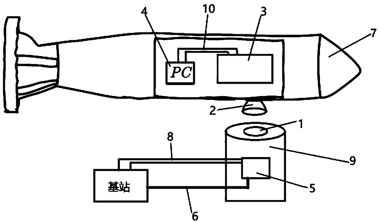
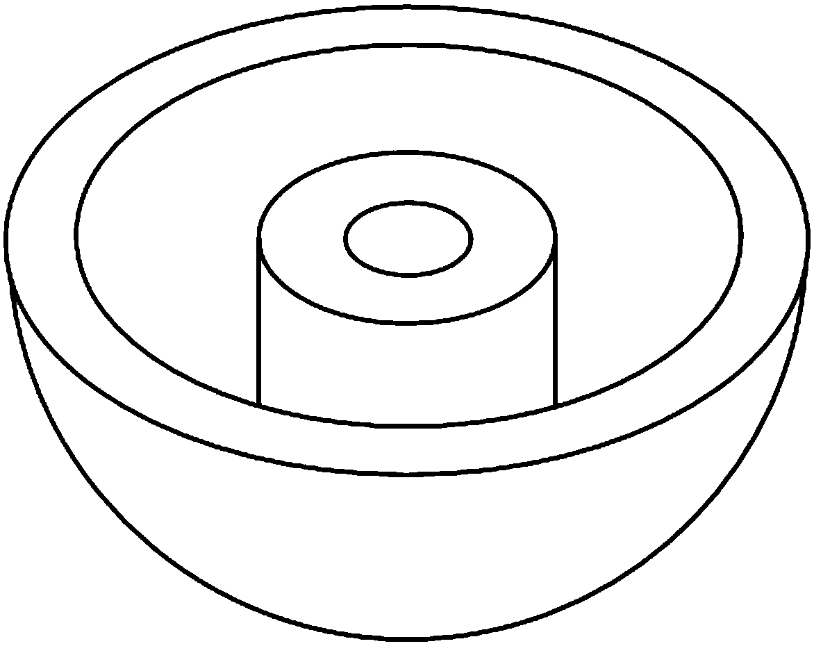
[0039] see figure 1 , figure 2 , which shows a schematic structural diagram of a coil-coupled under...


PUM


Abstract

The invention discloses a coil coupling type underwater wireless electric energy transmitter. The transmitter comprises a transmitting end and a receiving end; the transmitting end comprises a transmitting end coil, a transmitting end circuit board, a connecting cable, a first communication line and a transmitting end fixed point; the receiving end comprises a receiving end coil, a receiving end circuit board, an MCU and a second communication line; the receiving end circuit board, the MCU and the second communication line are arranged in an underwater vehicle; the receiving end circuit boardis connected with the MCU through the second communication line; the transmitting end circuit board is arranged in the transmitting end fixed point; and the transmitting end circuit board is connectedwith a base station through the connecting cable and the first communication line. An underwater wireless electric energy transmission system is optimized, so that the system is more humanized, and unnecessary electric energy loss is reduced; and a wireless communication function of the underwater wireless electric energy transmitter is set, so that great convenience is provided for the underwater wireless electric energy transmission system.

Description

technical field [0001] The invention belongs to the field of wireless power transmission, and relates to a coil-coupled underwater wireless power transmitter. Background technique [0002] The total area of ​​the ocean is 3.6×10⁸ square kilometers, accounting for 70.8% of the total area of ​​the earth. In this vast and rich ocean space, there are rich marine biological resources, ocean energy, ocean thermal energy and marine mineral resources. With the progress of industrialization and urbanization, the resources available on land are becoming less and less, and people are gradually paying attention to the effective use of marine resources. It can be said that the 21st century is the century when human beings march into the ocean. As an important means of exploring the ocean, even the only means in some cases, underwater vehicles are getting more and more attention. [0003] The main power supply mode of underwater vehicles is lithium-ion rechargeable battery, which has the...

Claims


Application Information

Patent Timeline
Patent Type & Authority Applications(China)
IPC IPC(8): H02J50/10
CPCH02J50/10
Inventor 白思佳方恒李兵史剑光余善恩
Owner HANGZHOU DIANZI UNIV
Why Eureka
Try Eureka