Anti-oscillation drying tank with compact structure

A technology with compact structure and anti-vibration, which is applied to the separation of dispersed particles, chemical instruments and methods, and separation methods. It can solve the problems of coalescing filter 2 particle clogging, increase and decrease the size of the drying cylinder, and achieve accurate opening pressure and ensure stability. sexual effect

Pending Publication Date: 2019-03-12
ZHEJIANG VIE SCI & TECH
View PDF2 Cites 0 Cited by
  • Summary
  • Abstract
  • Description
  • Claims
  • Application Information

AI Technical Summary

Problems solved by technology

Since gravity is used to collect the oil, it also limits the installation of the dryer cartridge to a near vertical
[0005] Third, the coalescing filter element 2 may be blocked by particles or by freezing during the filtration process
But this way has the following disadvantages, the location of the first check valve 16 has some disadvantages: the first check valve 16 is directly in contact with the incoming hot air, so it must be made of heat resistant material, which makes it more expensive
These dead space volumes reduce the amount of desiccant material 18 and increase the size of the drying cartridge

Method used


Image

  • Anti-oscillation drying tank with compact structure
  • Anti-oscillation drying tank with compact structure
  • Anti-oscillation drying tank with compact structure

Examples


Embodiment 1

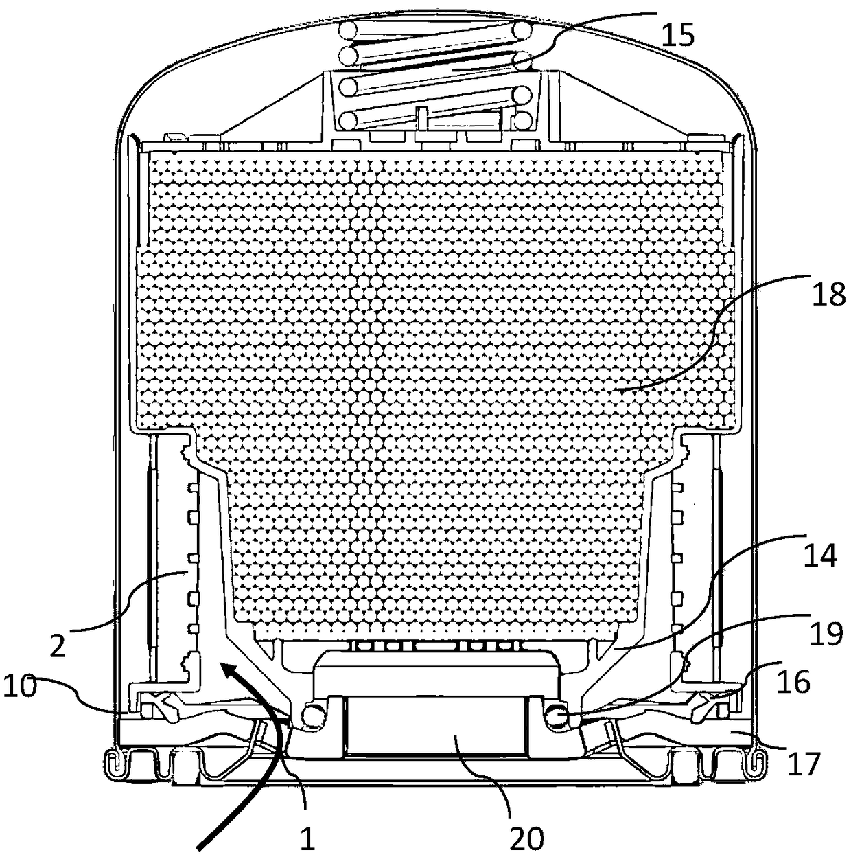
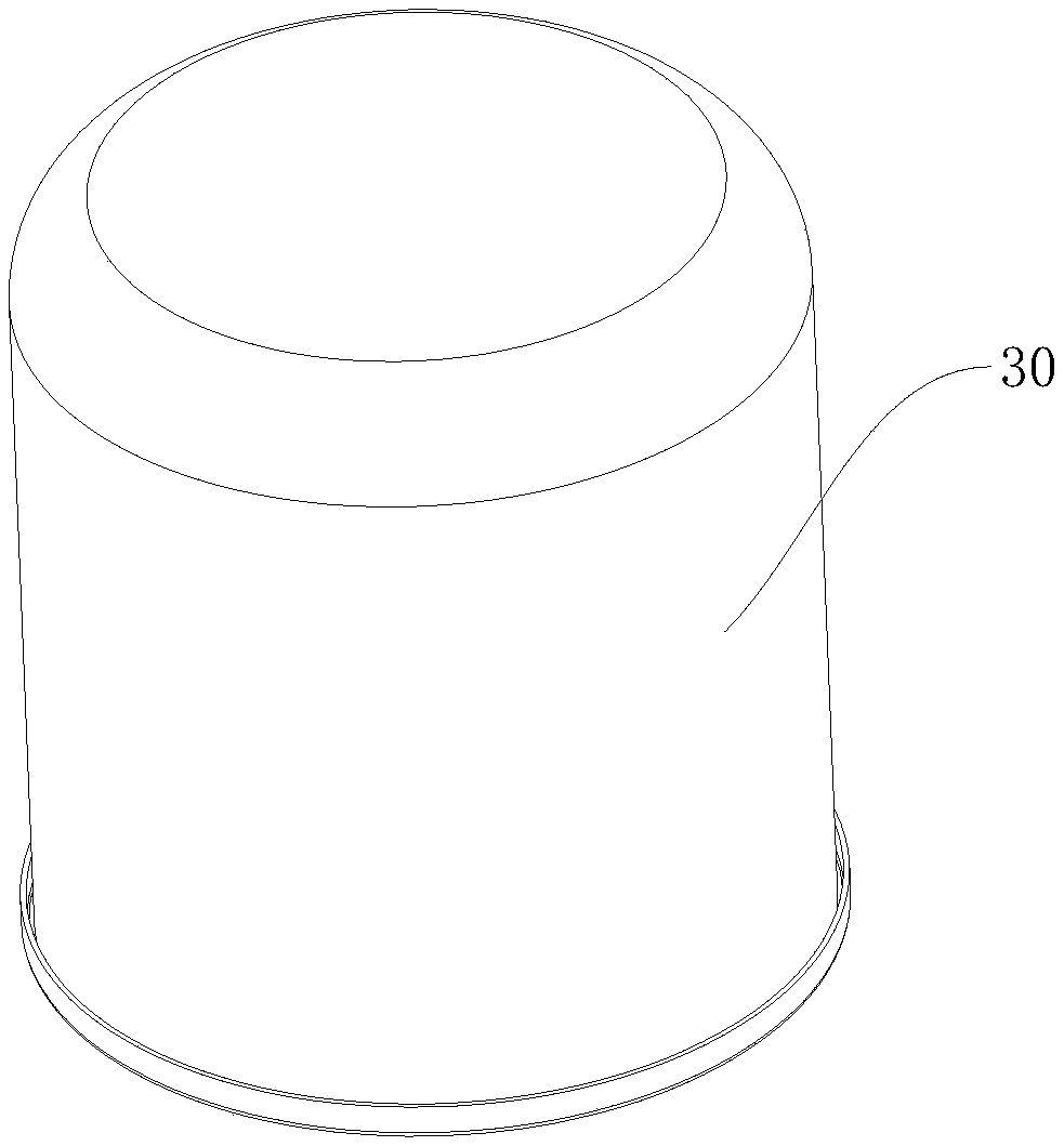
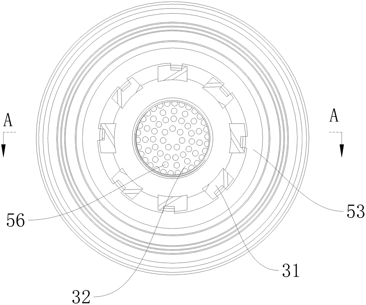
[0039] Such as Figure 2 to Figure 8 As shown, a compact anti-vibration drying tank includes a tank body 30 , wherein the tank body 30 is a cylindrical tank body 30 . The tank body 30 is provided with an air inlet 31 and an air outlet 32. The tank body 30 includes a base plate 53 at the bottom, wherein the air inlet 31 and the air outlet 32 ​​are all opened on the base plate 53, and the air outlet 32 ​​is positioned at the middle part of the base plate 53. The number of air ports 31 is evenly distributed around the air outlet 32 ​​. The tank body 30 is provided with a drying shell 33 , and the drying shell 33 is provided with a drying chamber 34 for containing desiccant, and the drying chamber 34 is placed in the drying chamber 34 . Wherein the drying shell 33 of the drying shell 33 is provided with a coalescing filter 35 for filtering oil particles, and the outer wall of the drying shell 33, the outer wall of the coalescing filter 35 and the inner wall of the tank body 30 en...

Embodiment 2

[0050] A compact anti-vibration drying tank. The difference between this embodiment and Embodiments 1 and 2 is that the coalescing filter element 41 is a cylindrical filter element whose inner diameter gradually increases along the vertical direction, and the first flexible element 46 and the second flexible element 48 are respectively connected to the two ends of the outer rib 46, and the limiting sleeve composed of the outer rib 60, the first flexible element 46 and the second flexible element 48 is detachably sleeved on the coalescing filter core. On the outside, the coalescing filter element 41 is placed in the annular slot surrounded by the first limiting plate 44 , the second limiting plate 45 and the inner rib 60 .

Embodiment 3

[0052] This embodiment provides an automobile vehicle equipped with the compact anti-vibration drying tank of Embodiment 1 or Embodiment 2.


PUM


Abstract

The invention relates to the field of air drying devices, and discloses an anti-oscillation drying tank with compact structure. The anti-oscillation drying tank comprises a heat exchange passage (36),wherein the heat exchange passage (36) is surrounded by the outside wall of a drying casing (33), the outside wall of a coalescent filter (35) and the inside wall of a tank body (30); the air flow isexhausted out of an air outlet (32) sequentially through an air inlet (31), the heat exchange passage (36), the coalescent filter (35) and a drying cavity (34); the drying casing (33) comprises a lower first casing body (37) and an upper second casing body (38), the second casing body (38) is positioned above the first casing body (37), the inner diameter of the second casing body (38) is smallerthan the inner diameter of the first casing body (37), and a connecting plate for connecting the first casing body (37) and the second casing body (38) is a transition plate (39); the coalescent filter (35) is positioned above the transition plate, and is sheathed at the exterior of the second casing body. The anti-oscillation drying tank is characterized in that the cost of a check valve is low,and the anti-oscillation drying tank is suitable for multiple types of installation space; the oscillation system is not produced, the service life is long, the cost is low, the size is small, and the like.

Description

technical field [0001] The invention relates to the field of vehicle compressed air drying and cleaning devices, in particular to a compact anti-vibration drying tank. Background technique [0002] The U.S. Patent Publication No. US20080289505A5 patent application document and the European Patent Grant Publication No. EP1495934B1 disclose a type of air dryer, which represents an existing air dryer for most of the global vehicle market. Technical air drying cylinder, the specific structure is as figure 1 shown. This kind of air drying cylinder has the following defects. [0003] First, since the air system is supplied by an air compressor. During compression, the compressed air is contaminated with oil droplets and hard carbon particles. Moisture in the air can also condense and form droplets. These water droplets can form emulsions with oil droplets. All of the aforementioned contamination is harmful to the components of the vehicle's air system, so it must be filtered...

Claims


Application Information

Patent Timeline
IPC IPC(8): B01D53/26B01D45/16
CPCB01D45/16B01D53/266
Inventor 马加什·克拉波特陈锋傅直全钱烜辉王保松陈钢强熊月明
Owner ZHEJIANG VIE SCI & TECH
Why Eureka
Try Eureka