
A liquid-sealed safety breathing valve with positive and negative pressure backflow

A breathing valve and negative pressure technology, applied in safety valves, valve devices, balance valves, etc., can solve problems such as inconvenient maintenance and operation of oil storage tank systems, loss of sealing function, safety issues, etc., and achieve active all-weather monitoring and trend recording , Reduce the volume of the valve body, and facilitate cleaning and maintenance

Active Publication Date: 2020-05-12
LIAONING UNIVERSITY OF PETROLEUM AND CHEMICAL TECHNOLOGY +1
View PDF6 Cites 0 Cited by
  • Summary
  • Abstract
  • Description
  • Claims
  • Application Information

AI Technical Summary

Problems solved by technology

[0003] Due to the internal structure of the existing traditional hydraulic safety valves used in oil tanks and other containers, when the positive pressure is opened, the pressure inside the tank will push the hydraulic pressure inside the hydraulic safety valve out of the valve, and when the negative pressure is opened, the sealing fluid will be discharged. Into the tank, so as to open the ventilation channel to achieve ventilation. When the sealing liquid is pressed out of the valve or discharged into the tank, the channel maintains a long-passing state and loses the sealing function. It is necessary to manually replenish the sealing liquid, and the maintenance workload is huge.
At the same time, when part of the sealing liquid in the valve is lost, the opening pressure of the traditional hydraulic safety valve decreases, which may open before the opening of the breathing valve, resulting in a decrease in the sealing pressure of the oil tank, resulting in increased leakage
Moreover, the sealing liquid directly splashed onto the top platform of the oil storage tank will cause environmental pollution and cause safety problems, and the sealing liquid discharged into the tank will pollute the storage medium in the tank, which will also bring a lot of inconvenience to the maintenance and operation of the oil storage tank system
[0004] To sum up, due to functional positioning and structural reasons, the traditional hydraulic safety valve has problems such as the loss of sealing fluid resulting in a decrease in opening pressure, large maintenance, unknown operating status, and environmental pollution.
Aiming at the main shortcomings of traditional hydraulic safety valves, there are existing patents to realize the collection and return of sealing liquid in the valve by setting up positive pressure liquid accumulation tanks and opening a number of oil return holes at the bottom of the tanks. However, due to the use of ventilation channels as return channels, resulting in Sealing liquid and air flow are mixed and entrained, which cannot fundamentally solve the problem of sealing liquid loss and splashing

Method used


Image

  • A liquid-sealed safety breathing valve with positive and negative pressure backflow
  • A liquid-sealed safety breathing valve with positive and negative pressure backflow
  • A liquid-sealed safety breathing valve with positive and negative pressure backflow

Examples


Embodiment 1

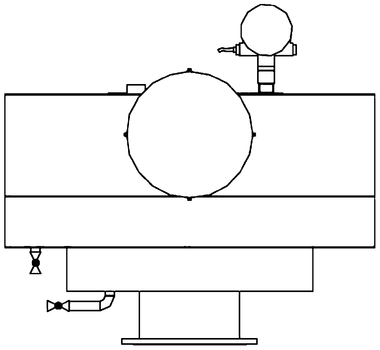
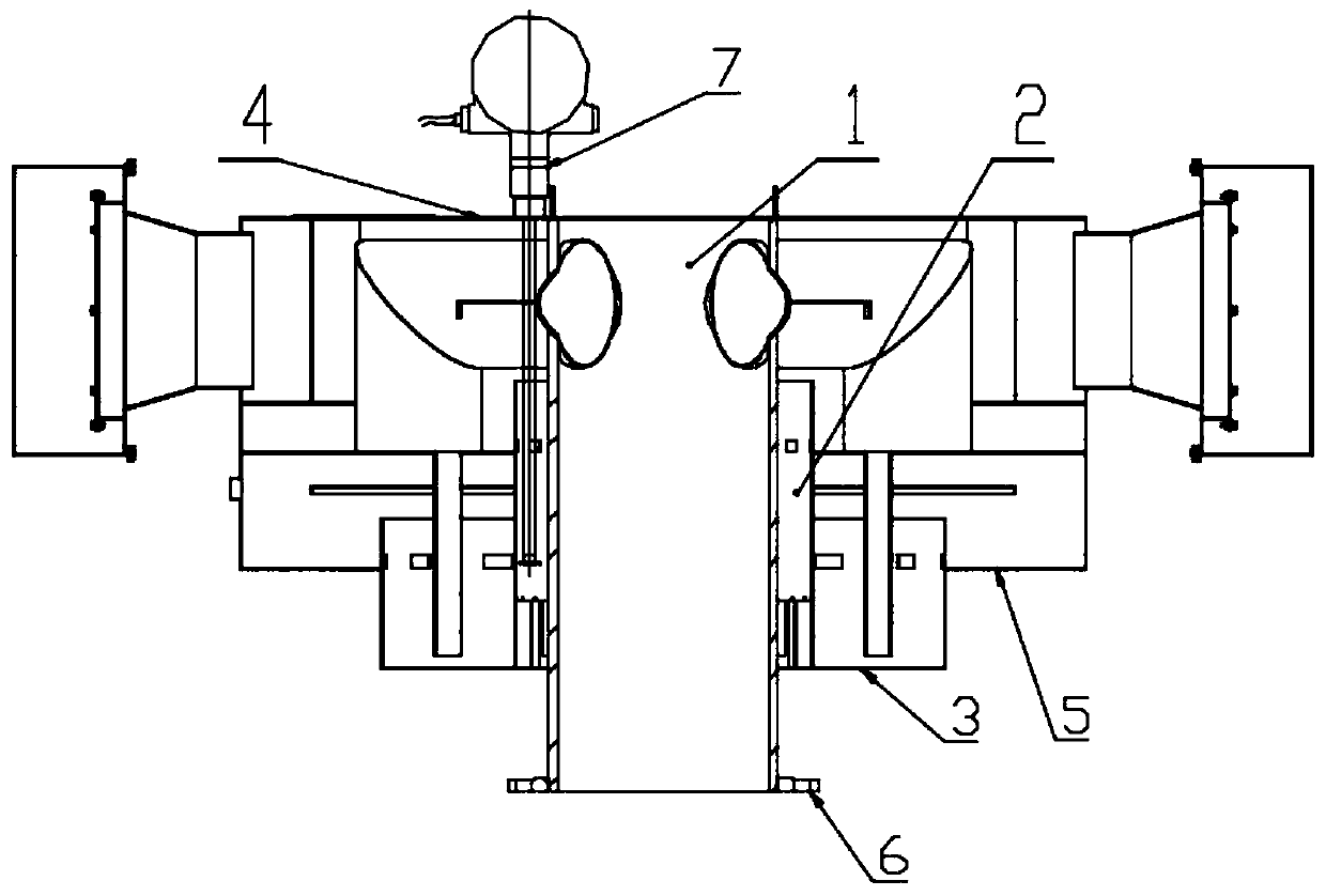
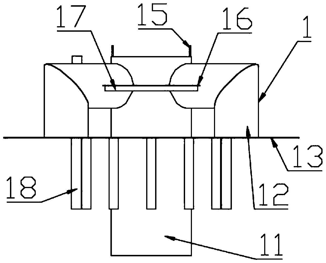
[0054] see Figure 1-22 , in an embodiment of the present invention, a liquid-sealed safety breathing valve for positive and negative pressure reflux, including a vent pipe assembly 1, a liquid barrier barrel assembly 2, a bottom plate assembly 3, an upper end cover plate assembly 4 and a negative pressure product Liquid tank assembly 5; the upper end cover plate assembly 4 and the bottom plate assembly 3 are respectively fixed on the upper and lower ends of the negative pressure liquid accumulation tank assembly 5 to form a cavity, and the ventilation pipe assembly 1 runs through the bottom plate assembly 3 And the liquid barrier barrel assembly 2 arranged in the cavity is fixed on the inner wall of the cavity through the bottom plate 13 of the positive pressure effusion tank. Several first elongated holes 211 on the liquid barrel assembly 2 communicate with the inner and outer sides of the liquid barrier barrel assembly 2, and the vent pipe assembly 1 communicates with the i...

Embodiment 2

[0074] The present invention also proposes another embodiment to perfect the application during the specific implementation process, specifically, it also includes a magnetostrictive liquid level gauge assembly 7, and the magnetostrictive liquid level gauge assembly 7 is set through the top cover 41 The liquid level gauge slot 413 is inserted in the liquid level gauge groove 25 arranged on the inside of the overnight barrel 21 .

[0075] Further, the magnetostrictive liquid level gauge assembly 7 includes a magnetostrictive liquid level gauge 71, a magnetostrictive liquid level gauge bottom plate 72 and a magnetostrictive liquid level gauge fixing plate 73, the magnetostrictive liquid level gauge The gauge bottom plate 72 is a thin plate with a hole in the middle and can be put into the liquid level gauge tank 25. The magnetostrictive liquid level gauge bottom plate 72 is fixed on the bottom of the magnetostrictive liquid level gauge 71 by bolts to ensure the magnetostrictive l...


PUM


Abstract

The invention relates to the field of oil and gas storage and transportation, in particular to a positive and negative pressure reflux liquid-seal safety breather valve. The breather valve comprises abreather pipe assembly, a liquid separation barrel assembly, a bottom plate assembly, an upper end cover plate assembly and a negative pressure liquid accumulation tank assembly, wherein the upper end cover plate assembly and the bottom plate assembly are fixed at the upper end and the lower end of the negative pressure liquid accumulation tank assembly correspondingly to form a cavity, the breather pipe assembly penetrates through the bottom plate assembly and the liquid separation barrel assembly arranged in the cavity and is fixed on the inner wall of the cavity through a bottom plate of apositive pressure liquid accumulation tank, the liquid separation barrel assembly penetrates through the bottom plate of the positive pressure liquid accumulation tank and communicate with the innerside and the outer side of the liquid separation barrel assembly through a plurality of first strip holes arranged on the liquid separation barrel assembly. According to the breather valve, when starting under positive pressure and negative pressure is conducted, the phenomenon that when a sealing liquid splashes out of the liquid-seal safety breather valve so as to pollute a top platform of a petroleum storage tank when the positive pressure and the negative pressure of the liquid-seal safety breather valve exceed limit is avoided, and the breather valve has the function that the sealing liquid automatically flows back into the cavity and repeatedly forms sealing when the positive pressure and the negative pressure exceeds the limits.

Description

technical field [0001] The invention relates to the field of oil and gas storage and transportation, in particular to a liquid-sealed safety breathing valve that can realize the automatic return of sealing liquid to the inner cavity through the structure of the return pipe after the positive and negative pressure is opened. Background technique [0002] The hydraulic safety valve is an important accessory to protect the safety of the storage tank in the petroleum storage and transportation system. It belongs to the category of automatic valves. The main structure and use requirements of the valve. The traditional hydraulic safety valve is used together with the mechanical breathing valve, and its opening pressure is set higher than that of the mechanical breathing valve, so it does not open when the mechanical breathing valve is working normally, and plays a second protective role. The traditional hydraulic safety valve is usually installed on the top of the oil tank, and i...

Claims


Application Information

Patent Timeline
Patent Type & Authority Patents(China)
IPC IPC(8): F16K17/192
CPCF16K17/192
Inventor 李维军崔学文景家峰
Owner LIAONING UNIVERSITY OF PETROLEUM AND CHEMICAL TECHNOLOGY
Learn More