Supercharge Your Innovation With Domain-Expert AI Agents!

Turning processing equipment for electric rotary cylindrical spindle head

A technology for electric rotating and processing equipment, applied in turning equipment, turning equipment, metal processing equipment, etc., can solve the problems of low construction efficiency, difficult to guarantee construction accuracy, and difficult to disassemble and replace the turning head, and to simplify the movement of the column and Rotating operation, improving construction efficiency, quality and efficiency, and the effect of improving construction efficiency and construction accuracy

Pending Publication Date: 2019-03-12
罗甸县金泰模具机械制造有限公司
View PDF0 Cites 0 Cited by
  • Summary
  • Abstract
  • Description
  • Claims
  • Application Information

AI Technical Summary

Problems solved by technology

Due to the large size and complex structure of existing cylindrical grinders, the turning head is difficult to disassemble and assemble. During the processing and production process, the turning head is often shut down for maintenance due to damage to the turning head; and it is difficult to move the column axially during construction in a narrow processing area. At the same time, it is difficult to perform manual rotation, and the rotation accuracy is low, not only the construction efficiency is not high, but the construction accuracy is also difficult to guarantee
[0003] Therefore, in the existing cylindrical grinding machine, the connection mode of the turning head is more complicated, the turning method is more complicated, and the turning head is difficult to disassemble and replace; The efficiency is not high, and the construction accuracy is poor

Method used


Image

  • Turning processing equipment for electric rotary cylindrical spindle head
  • Turning processing equipment for electric rotary cylindrical spindle head
  • Turning processing equipment for electric rotary cylindrical spindle head

Examples


Embodiment Construction

[0031] The present invention will be further described below in conjunction with the accompanying drawings and embodiments, but not as a basis for limiting the present invention.

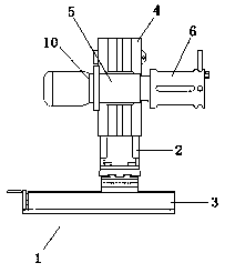
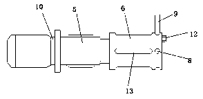
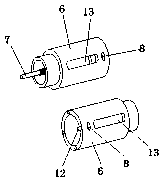
[0032] Example. Electric rotary external spindle head turning equipment, such as Figure 1 to Figure 11 As shown, a base 1 is included, and a column 2 is arranged on the top of the base 1. The base 1 includes a horizontal screw feed seat 3, and a column rotation mounting platform is arranged above the horizontal screw feed base 3. The column rotation mounting table includes a horizontal The screw feed seat 3 is a mobile rotary connector that is movably connected, and a column screw feed device is arranged above the mobile rotary connector, and the column screw feed device is fixedly connected with the column 2; a slider 4 is provided on one side of the column 2, The slide block 4 is provided with a shaft head turning device, and the shaft head turning device includes a connecting installation shaft...


PUM


Abstract

The invention discloses turning processing equipment for an electric rotary cylindrical spindle head. The turning processing equipment comprises a base, wherein a stand column is arranged above the base; the base comprises a transverse lead screw feeding base; a stand column rotary mounting table is arranged above the transverse lead screw feeding base; the stand column rotary mounting table comprises a movable rotary connector which is movably connected with the transverse lead screw feeding base; a stand column lead screw feeding device is arranged above the movable rotary connector; the stand column lead screw feeding device is fixedly connected with the stand column; a slide block is arranged at one side of the stand column; and a spindle head turning device is arranged on the slide block. The turning processing equipment is relatively small in size, is convenient in carrying, is convenient in use, is easily dismounted, is convenient in maintaining and replacing, meets cylindricalspindle head turning construction requirements, and improves construction efficiency quality and efficiency; and meanwhile, stand column movement and rotation operation is simplified, rotation precision is relatively high, and construction efficiency and construction precision are improved.

Description

technical field [0001] The invention relates to an outer cylindrical grinding machine, in particular to an electric rotating outer cylindrical shaft head turning processing equipment. Background technique [0002] Cylindrical grinding machine is a grinding machine for processing the outer surface and shoulder end surface of the workpiece cylindrical, conical or other shapes; it is the most widely used and can process various cylindrical conical outer surfaces and shoulder end surface grinding machines. Due to the large size and complex structure of existing cylindrical grinders, the turning head is difficult to disassemble and assemble. During the processing and production process, the turning head is often shut down for maintenance due to damage to the turning head; and it is difficult to move the column axially during construction in a narrow processing area. , At the same time, it is difficult to perform manual rotation, and the rotation accuracy is low, not only the cons...

Claims


Application Information

Patent Timeline
IPC IPC(8): B23B5/08
CPCB23B5/08B23Q1/26B23Q5/40
Inventor 刘海
Owner 罗甸县金泰模具机械制造有限公司
Features
  • R&D
  • Intellectual Property
  • Life Sciences
  • Materials
  • Tech Scout
  • Unparalleled Data Quality
  • Higher Quality Content
  • 60% Fewer Hallucinations
Learn More