
String clip nail feeding device

A line card and equipment technology, applied in metal processing equipment, metal processing, manufacturing tools, etc., can solve problems such as production efficiency, product quality and safety factor cannot be guaranteed, production efficiency improvement is not obvious, and manual assistance is required to achieve Ease of maintenance and repair, reduction of production costs, and improvement of production efficiency

Inactive Publication Date: 2019-03-12
宜昌捷龙电气有限公司
View PDF0 Cites 2 Cited by
  • Summary
  • Abstract
  • Description
  • Claims
  • Application Information

AI Technical Summary

Problems solved by technology

In the past, the steps of inserting steel nails into plastic line cards were mostly done manually, and the production efficiency, product quality, and safety factor could not be guaranteed.
In order to improve production efficiency, and thus increase output and benefits, some manufacturers also use manipulators to assist nail penetration, but the manipulator is a precision instrument, and each time it needs to be aligned and positioned, and the direction of the steel nails and plastic wire cards must be ensured. Not only the equipment cost is high, Manual assistance is still required, and the improvement in production efficiency is not obvious

Method used


Image

  • String clip nail feeding device
  • String clip nail feeding device
  • String clip nail feeding device

Examples


Embodiment Construction

[0016] In order to make the technical means, creative features, goals and functions achieved by the present invention clearer and easier to understand, the present invention will be further elaborated below in conjunction with the accompanying drawings and specific embodiments:

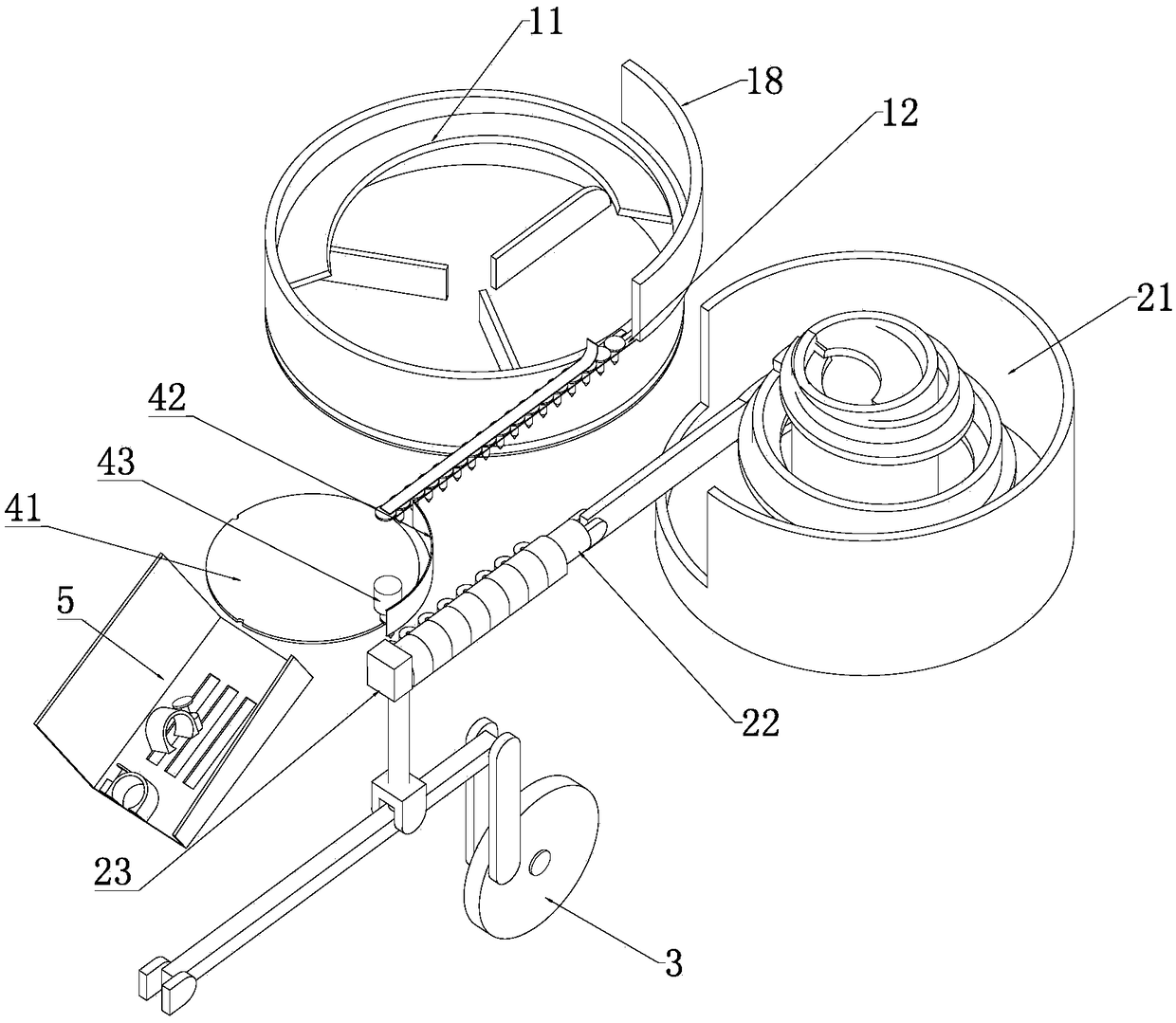
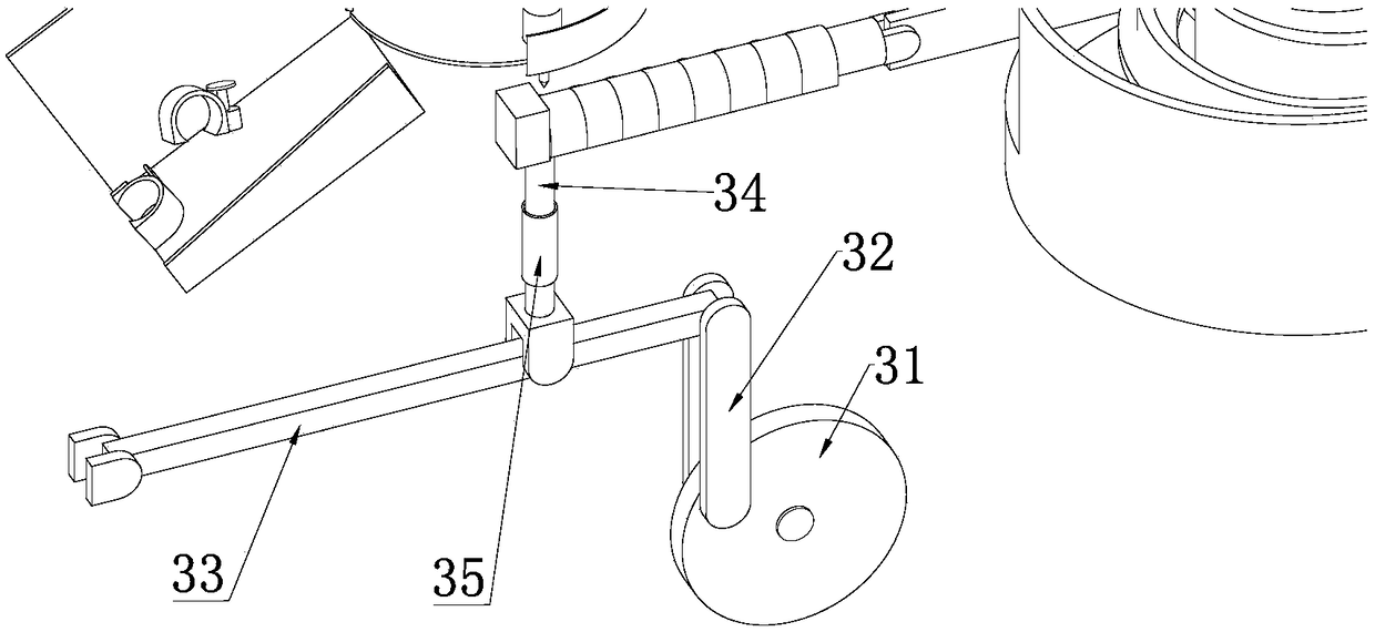
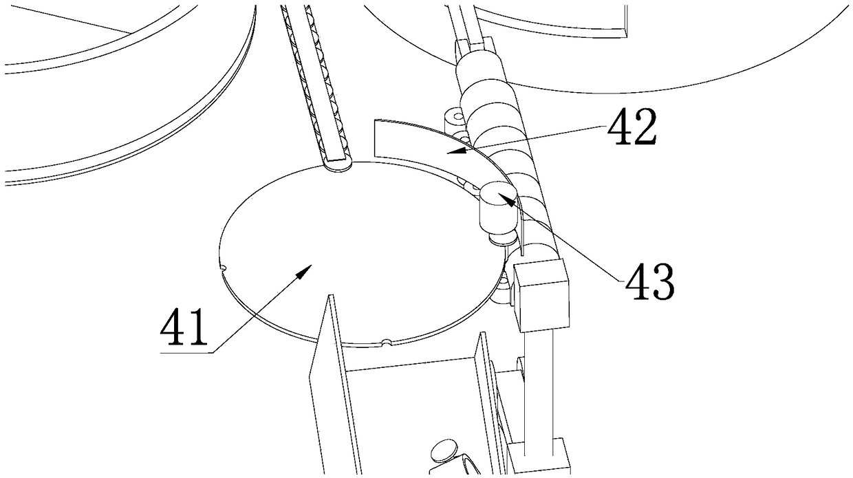
[0017] combine figure 1 , the invention discloses a wire card nailing device, comprising a bracket (not shown in the figure), a nailing mechanism fixed on the bracket, and a steel nail input mechanism and a plastic wire card input mechanism connected with the nailing mechanism; The nailing mechanism includes a steel nail clamping device, a nail hammer 43 fixedly arranged above the steel nail clamping device, and a driving device for making the plastic wire clip hit the steel nail directly below the nail hammer 43 from bottom to top; The steel nail input mechanism includes a rotating disk 11 for accommodating and arranging steel nails and a steel nail delivery arm 12 connecting the rotating disk 11 and...


PUM


Abstract

The invention provides a string clip nail feeding device. The string clip nail feeding device comprises an nail feeding mechanism, a steel nail input mechanism and a plastic string clip input mechanism, wherein the steel nail input mechanism and the plastic string clip input mechanism are connected with the nail feeding mechanism; the nail feeding mechanism comprises a steel nail clamping device,a knocking hammer fixed above the steel nail clamping device, and a driving device used for enabling the plastic string clip to collide with the steel nail located under the knocking hammer in a collision manner from bottom to top; the steel nail input mechanism comprises a rotating disc and a steel nail conveying arm; the plastic string clip input mechanism comprises a vibration disc and a plastic string clip transportation arm; one end of the plastic string clip conveying arm is hinged to the vibration disc, and the other end of the plastic string clip conveying arm swings up and down underthe driving of the driving device; a stop block is fixed at the free end of the plastic string clip transportation arm, so that when the plastic string clip conveying arm swings upwards, the steel nails under the nail knocking hammer are nailed into the nail holes of the plastic string clip close to the stop block. According to the string clip nail feeding device, the continuous full-automatic production of the nail feeding on the string clip is realized by adopting a simple mechanical structure, the production efficiency is remarkably improved, the production cost is reduced, moreover, the device is simple in structure and easier to maintain and maintain.

Description

technical field [0001] The invention belongs to the field of electrical accessories production, in particular to an automatic device for nailing plastic wire clips. Background technique [0002] During the decoration process, when laying wires or network cables along the wall, the most commonly used accessories are plastic cable clips with steel nails. In the past, the steps of inserting steel nails into plastic line cards were mostly done manually, and the production efficiency, product quality, and safety factor could not be guaranteed. In order to improve production efficiency, and thus increase output and benefits, some manufacturers also use manipulators to assist nail penetration, but the manipulator is a precision instrument, and each time it needs to be aligned and positioned, and the direction of the steel nails and plastic wire cards must be ensured. Not only the equipment cost is high, Human assistance is still required, and the improvement in production efficien...

Claims


Application Information

Patent Timeline
IPC IPC(8): B23P19/00B23P19/02
CPCB23P19/00B23P19/001B23P19/02
Inventor 廖文翔
Owner 宜昌捷龙电气有限公司
Learn More