Eureka AIR delivers breakthrough ideas for toughest innovation challenges, trusted by R&D personnel around the world.

Lateral suction and pulling type fabric automatic ironing equipment

An ironing equipment and automatic technology, applied in the direction of drying fabrics, textiles and papermaking, fabric surface trimming, etc. Effect

Active Publication Date: 2019-03-12
四会市永利布匹定型有限公司
View PDF5 Cites 3 Cited by
  • Summary
  • Abstract
  • Description
  • Claims
  • Application Information

AI Technical Summary

Problems solved by technology

[0003] 1. The cloth ironing equipment in the prior art adopts the automatic ironing method of conveying and flowing, that is, pulling one end of the cloth to iron the cloth regularly, but due to the pulling force at the end and the end, the cloth often produces horizontal arching Or sag, the ironing force directly pressed down during ironing will iron it to form wrinkles, which will affect the flatness of the cloth;
[0004] 2. After ironing, there will be hot moisture on the fabric. After the ironing is finished, the fabric will be rolled up directly, and the hot moisture will be rolled up inside the fabric together. It is often used to dehumidify by blowing or pumping air to remove moisture. Solve this problem, but the wind generated by it will affect the uniformity of the cloth when it is rolled

Method used


Image

  • Lateral suction and pulling type fabric automatic ironing equipment
  • Lateral suction and pulling type fabric automatic ironing equipment
  • Lateral suction and pulling type fabric automatic ironing equipment

Examples


Embodiment Construction

[0030] In order to make the technical means, creative features, goals and effects achieved by the present invention easy to understand, the present invention will be further described below in conjunction with specific embodiments.

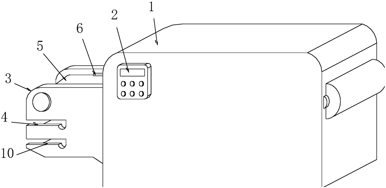
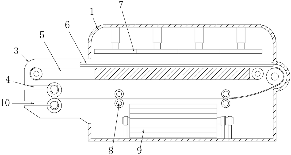
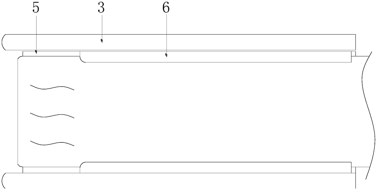
[0031] Such as Figure 1-Figure 7 As shown, the present invention provides a technical solution for automatic ironing equipment for laterally absorbing and pulling cloth:

[0032] An automatic ironing device for laterally sucking and pulling cloth, the structure of which includes a main box 1, a control panel 2, a workbench 3, a release roller slot 4, a conveying mechanism 5, a lateral sucking device 6, and an ironing device 7 , the lead-out mechanism 8, the heat and moisture removal mechanism 9, the locking groove 10 of the winding cloth roller, the control panel 2 is embedded in the upper left corner of the front surface of the main box 1, and the workbench 3 is arranged on the left side of the main box 1 and Inside, the release cloth roller lo...


PUM


Abstract

The invention discloses lateral suction and pulling type fabric automatic ironing equipment. The lateral suction and pulling type fabric automatic ironing equipment structurally comprises a main machine box, a control panel, a worktable, a fabric release roll clamping groove, a conveying mechanism, a lateral suction and pulling device, an ironing device, a leading-out mechanism, a hot moisture removal mechanism, and a fabric uncoiling roll clamping groove. The lateral suction and pulling type fabric automatic ironing equipment has the advantages that by arranging the lateral suction and pulling equipment, a mode of negative-pressure suction and pulling type and the crawler pressing and pulling type is adopted, the edges of the front part and back part of the fabric are pulled, and the pulling forces at the starting end and finishing end of the automatic ironing equipment are utilized to pull the surrounding edges of the fabric, so that the fabric can be more flatly ironed in the ironing process; by arranging the hot moisture removal mechanism, the remaining hot moisture in the ironing process can be absorbed by lime, the hot moisture removal mechanism is arranged in a spiral way and is in short-distance contact with the fabric to quickly absorb and remove the hot moisture, then the moisture is prevented, and the dampness and mildewing of the directly coiled fabric due to coiling of the hot moisture into the fabric can be prevented.

Description

technical field [0001] The invention relates to the field of ironing equipment, more specifically, an automatic ironing equipment for laterally sucking and pulling cloth. Background technique [0002] In order to facilitate more accurate cutting during later stage cloth production, the cloth then needs to be ironed, but the cloth ironing equipment of the prior art has the following defects: [0003] 1. The cloth ironing equipment in the prior art adopts the automatic ironing method of conveying and flowing, that is, pulling one end of the cloth to iron the cloth regularly, but due to the pulling force at the end and the end, the cloth often produces horizontal arching Or sag, the ironing force directly pressed down during ironing will iron it to form wrinkles, which will affect the flatness of the cloth; [0004] 2. After ironing, there will be hot moisture left on the fabric. After the ironing is finished, the fabric will be rolled up directly, and the hot moisture will be...

Claims


Application Information

Patent Timeline
IPC IPC(8): D06C15/00
CPCD06C15/00D06C2700/09D06C2700/10
Inventor 陈溢
Owner 四会市永利布匹定型有限公司
Why Eureka
Eureka Blog
Learn More