Bone fracture reduction device for four limb long bone diaphysis

A reduction device and technology for long bones, applied in the field of medical devices, can solve the problems of difficult fracture reduction, easy deflection of instruments, and limited accuracy.

Active Publication Date: 2019-03-15
HENAN PROVINCE HOSPITAL OF TCM THE SECOND AFFILIATED HOSPITAL OF HENAN UNIV OF TCM
View PDF18 Cites 3 Cited by
  • Summary
  • Abstract
  • Description
  • Claims
  • Application Information

AI Technical Summary

Problems solved by technology

[0004] In view of the above situation, in order to overcome the defects of the prior art, the present invention provides a long bone fracture r

Method used


Image

  • Bone fracture reduction device for four limb long bone diaphysis
  • Bone fracture reduction device for four limb long bone diaphysis
  • Bone fracture reduction device for four limb long bone diaphysis

Examples


Embodiment 1

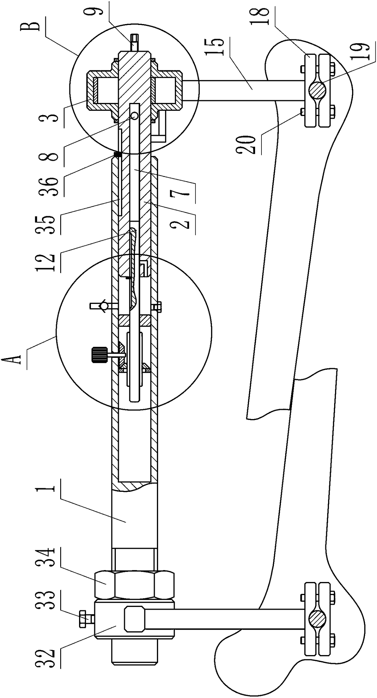
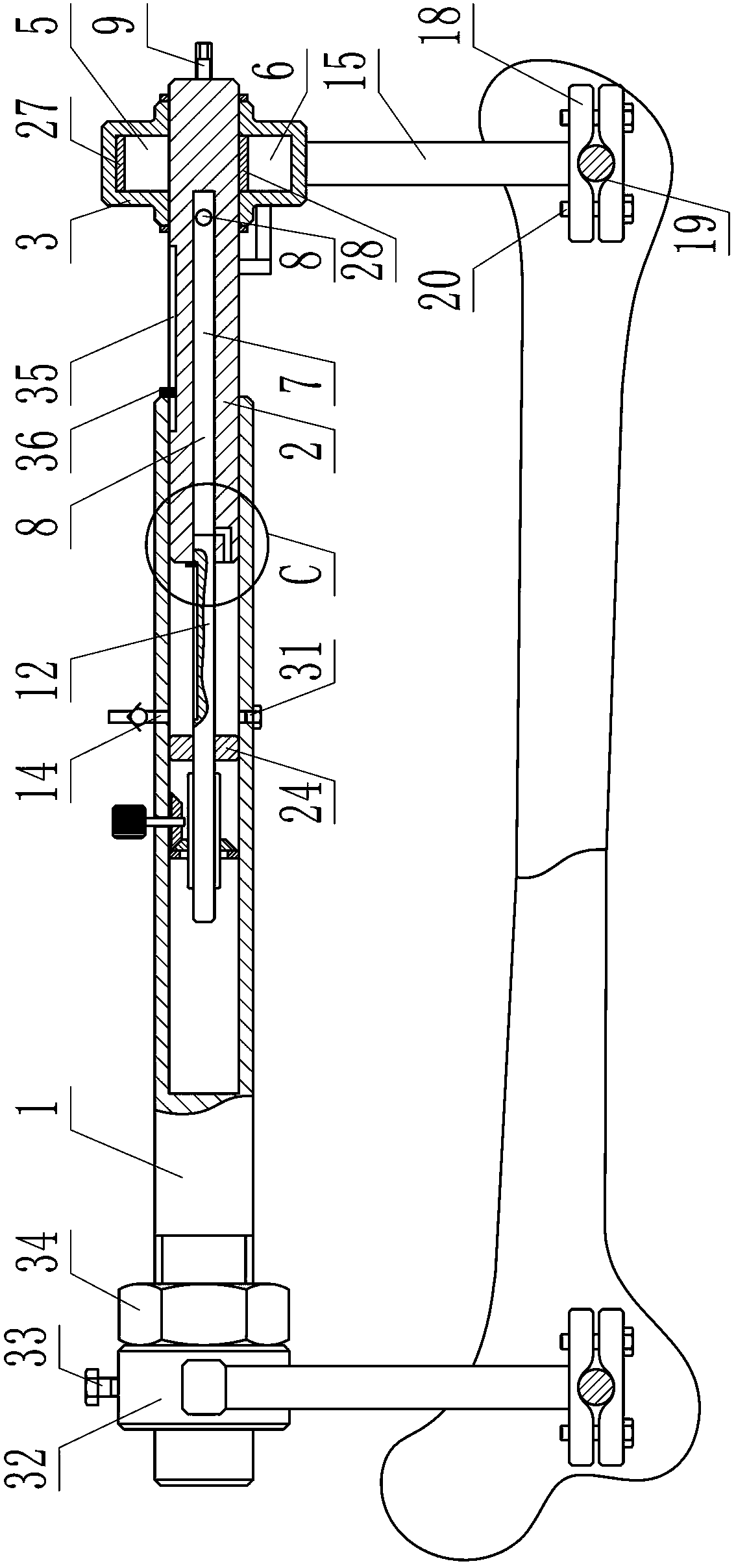
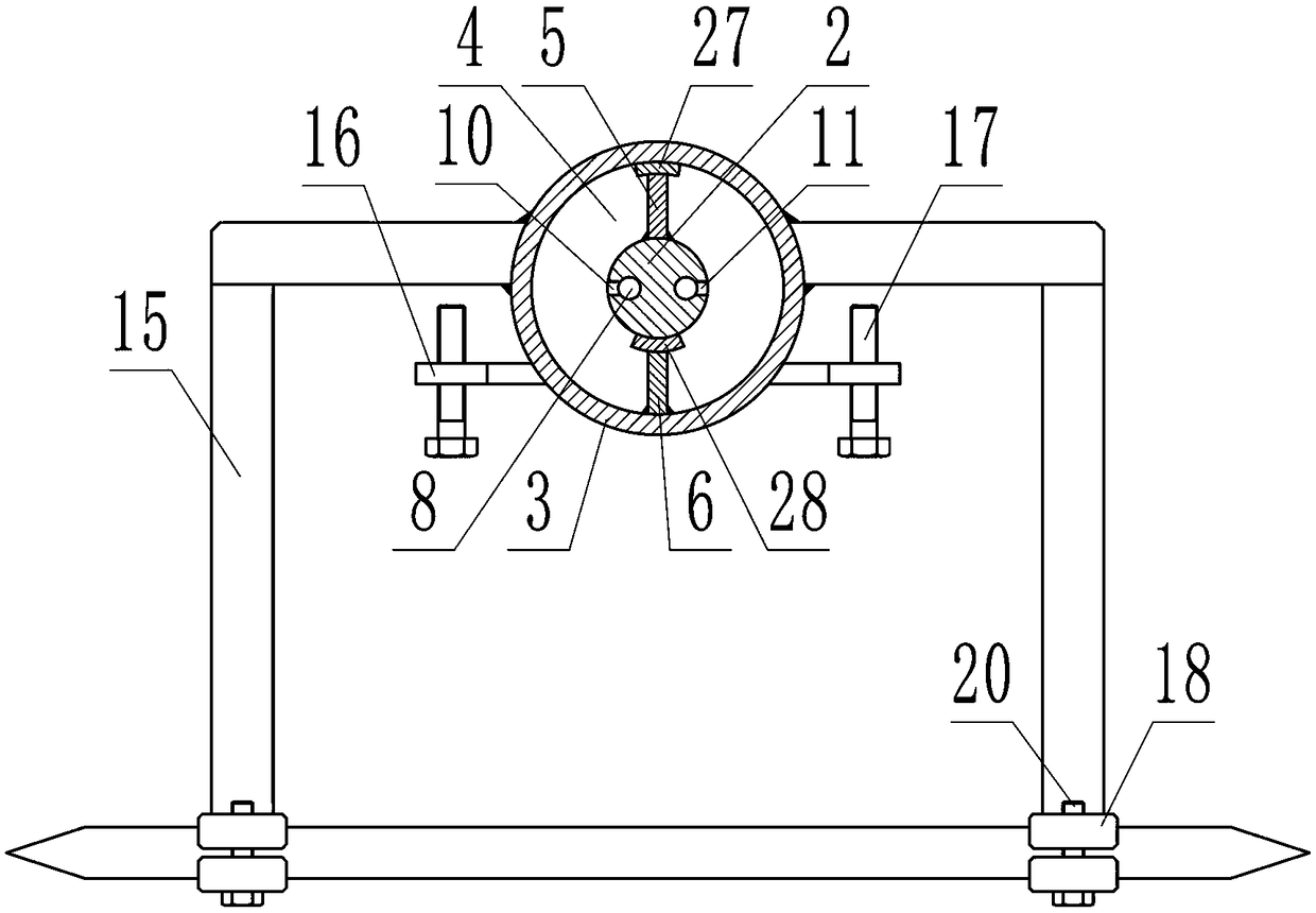
[0016] Embodiment 1, the present invention includes a support rod 1, the support rod 1 is a hollow structure with a closed left end, a telescopic rod 2 is installed in the cavity of the support rod 1, the telescopic rod 2 can slide in the support rod 1 and the right end protrudes for support Outside the rod 1, the right end of the telescopic rod 2 is fitted with a cylindrical housing 3 that is coaxial with it and can rotate around the telescopic rod 2. The left and right ends of the housing 3 are attached to the outer wall of the telescopic rod 2. The inner diameter of the middle section is larger than the outer diameter of the telescopic rod 2 so as to form an annular cavity 4 with the telescopic rod 2, and a vertical first partition 5 and a vertical second partition are installed in the cavity 4 6. The first partition 5 is fixed at the upper quadrant of the telescopic rod 2, and the second partition 6 is fixed at the lower quadrant of the housing 3. The first partition and th...

Embodiment 2

[0017] Embodiment 2. On the basis of Embodiment 1, the traction bow includes a door-shaped bow frame 15, one of which is fixed on the outer wall of the housing 3 and the vertical rods on both sides of the bow frame 15 Parts are symmetrically located on the front and rear sides of the housing 3, and another bow frame 15 is fixed on the left end of the support rod 1 and the vertical rods on both sides of the bow frame 15 are symmetrically located on the front and rear sides of the support rod 1. Each bow frame 15 A clamping device is installed at the lower ends of the side vertical bar parts.

Embodiment 3

[0018] Embodiment 3, on the basis of Embodiment 1, the limiting device includes two horizontal fixing plates 16, both of which are located under the crossbar part of the right-end bow frame 15 and symmetrically separated from the two sides of the housing 3. side, two fixed plates 16 are all fixed on the outer wall of the telescopic rod 2, and a vertical limit bolt 17 is screwed on each fixed plate 16; The rotation angle is limited.


PUM


Abstract

The invention relates to a bone fracture reduction device for a four limb long bone diaphysis. The problems are solved that during bone fracture reduction, difficulty is high, precision is limited, and an instrument easily declines; in the technical solution scheme, the bone fracture reduction device comprises a hollow supporting rod, a telescopic rod is installed in a cavity of the supporting rod, a cylindrical shell sleeves the right end of the telescopic rod, an annular cavity is formed between the shell and the telescopic rod, a first vertical partitioning plate and a second vertical partitioning plate are installed in the cavity, the two partitioning plates divide the cavity into a front semicircular part and a rear semicircular part which are separately closed, an air channel capableof being switched and communicated with the two parts of the cavity is formed in the telescopic rod, the telescopic rod moves rightwards by a certain distance to start the air channel, an air inlet hole communicated with the internal cavity of the supporting rod is formed in the side wall of the supporting rod, and traction bows are installed at the left end of the supporting rod and on the outerwall of the shell respectively. Through pre-adjustment, the device greatly lowers the difficulty of bone fracture reduction in an operation, improves reduction precision, and has no declining torque.

Description

technical field [0001] The invention relates to the field of medical devices, in particular to a device for reducing fractures of limbs and long bones. Background technique [0002] Fracture of long bones of extremities is the most common form of fracture. Due to the pulling of muscles and the movement of limbs after fracture, it is easy to produce shortening deformity and rotational deformity. In this case, the broken bone must be reset and the deformity corrected to make the alignment and alignment good after healing without affecting the quality of life of the patient, otherwise complications such as poor alignment and malunion may lead to traumatic arthritis or osteoarthritis Inflammation seriously affects the limb function and quality of life of patients. [0003] The current fracture reduction instruments are all reset devices fixed on both ends of the broken bone through traction pins, and then reset. The length of the broken bone and the angle of rotation are adjust...

Claims


Application Information

Patent Timeline
IPC IPC(8): A61B17/88
CPCA61B17/8866
Inventor 齐秀春李沛陈昕曹玉净李扬王前进艾进伟宋鹏
Owner HENAN PROVINCE HOSPITAL OF TCM THE SECOND AFFILIATED HOSPITAL OF HENAN UNIV OF TCM
Why Eureka
Try Eureka