
Knock-out barrel

The technology of a shakeout machine and a drum is applied in the field of foundry equipment, which can solve the problems of difficult collection of molding sand and diffusion of dust into the air, etc., and achieve the effects of improving impact resistance, reducing production costs of enterprises, and reducing water resources utilization.

Inactive Publication Date: 2019-03-15
XINHUANG YUANDA MACHINERY CASTING
View PDF7 Cites 0 Cited by
  • Summary
  • Abstract
  • Description
  • Claims
  • Application Information

AI Technical Summary

Problems solved by technology

[0002] Casting is a commonly used metal thermal processing process, that is, the metal is smelted into a liquid and then poured into a mold made of molding sand. After the liquid metal is cooled and solidified in the cavity in the mold, in order to obtain the casting, the molding sand needs to be removed from the casting. The surface is separated. The existing method is to use the vibration and impact generated by the shakeout machine to complete the shakeout. Compared with the vibrating shakeout machine, the drum shakeout machine has the advantages of easy noise control and good working conditions, so the application More and more widely, the existing drum shakeout machine is equipped with a dust removal fan at the inlet and outlet of the drum to collect the dust overflowing from the outlet of the drum, but due to the excessive amount of dust, the dust will still diffuse into the air and fall from the casting at the same time. Falling sand is difficult to collect

Method used


Image

  • Knock-out barrel
  • Knock-out barrel

Examples


Embodiment Construction

[0020] In order to enable those skilled in the art to better understand the technical solution of the present invention, the present invention will be described in detail below in conjunction with the accompanying drawings. The description in this part is only exemplary and explanatory, and should not have any limiting effect on the protection scope of the present invention. .

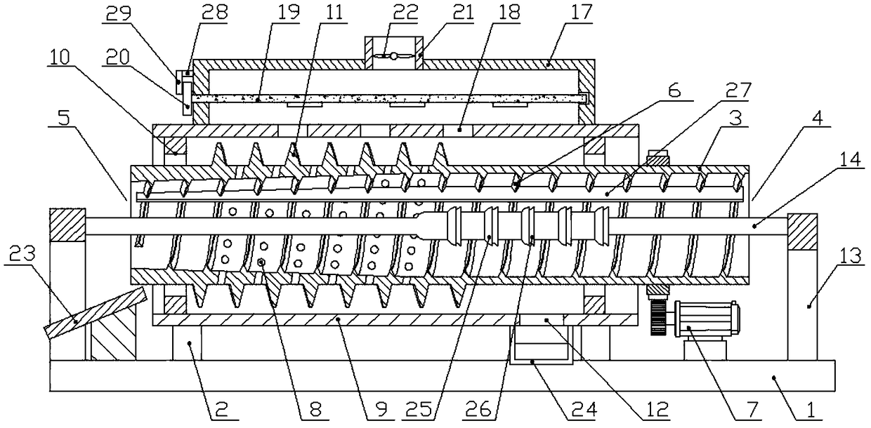
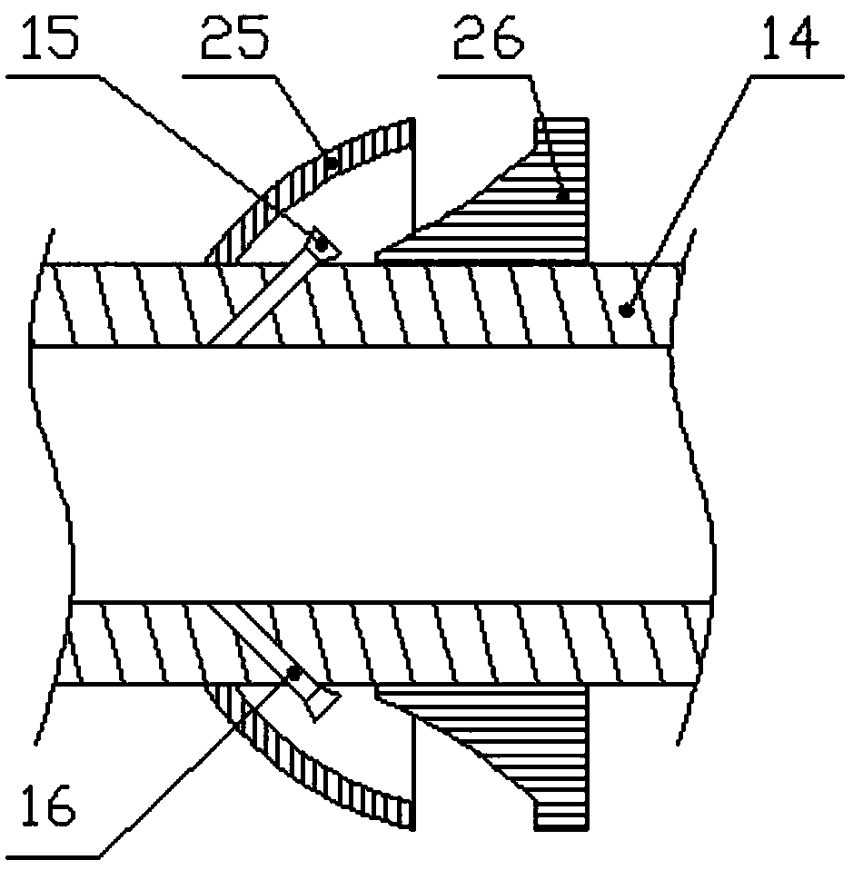
[0021] like Figure 1-Figure 2 As shown, the specific structure of the present invention is as follows: it includes a base 1, the middle part of the upper end of the base 1 is provided with a support seat 2 at intervals, and a cylindrical roller 3 is arranged above the support seat 2, and the two ends of the roller 3 are open. One end is set as the feed end 4, and the other end is set as the discharge end 5. The casting mold enters the drum 3 from the feed end 4, and the casting after falling out is discharged from the discharge end 5. The inner wall of the drum 3 is provided with an inner Thread 6, t...


PUM


Abstract

The invention discloses a knock-out barrel. The knock-out barrel comprises a base, a supporting base is arranged in the middle of the upper end of the base in a spaced manner, a roller is arranged above the supporting base, an inner thread is arranged on the inner wall of the roller, a driving mechanism for driving the roller to rotate is arranged at the upper end of the base, a sand discharging hole is formed in the position, on the side of the discharging end, of the side wall of the roller, the supporting base is arranged at the upper end of the base, the upper end of the supporting base isprovided with an outer pipe with two ends opened, the roller is arranged in the outer pipe, an outer thread is arranged on the outer wall of the roller, a sand discharging hole is formed in the position, on the far side of the discharging end, of the bottom wall of the outer pipe, supports are arranged at the positions, on the two sides of the open ends of the outer pipe, of the upper end of thebase, a ventilation pipe with the hollow inner is arranged between the supports on the two sides, nozzles are formed in the position of the segment, located in the roller, of the side wall of the ventilation pipe, and a dust removal device is arranged on the upper end of the outer pipe. The knock-out barrel can easily collect molding sand, and meanwhile it is ensured that the dust cannot flow out.

Description

technical field [0001] The invention relates to the field of casting equipment, in particular to a drum shakeout machine. Background technique [0002] Casting is a commonly used metal thermal processing process, that is, the metal is smelted into a liquid and then poured into a mold made of molding sand. After the liquid metal is cooled and solidified in the cavity in the mold, in order to obtain the casting, the molding sand needs to be removed from the casting. The surface is separated. The existing method is to use the vibration and impact generated by the shakeout machine to complete the shakeout. Compared with the vibrating shakeout machine, the drum shakeout machine has the advantages of easy noise control and good working conditions, so the application More and more widely, the existing drum shakeout machine is equipped with a dust removal fan at the inlet and outlet of the drum to collect the dust overflowing from the outlet of the drum, but due to the excessive amo...

Claims


Application Information

Patent Timeline
Patent Type & Authority Applications(China)
IPC IPC(8): B22D29/00
CPCB22D29/00
Inventor 张勇
Owner XINHUANG YUANDA MACHINERY CASTING
Learn More