Robot joint variable rigidity module based on cam type lever structure

A robot joint and cam type technology, applied in the field of robotics, can solve the problems of small stiffness adjustment range, large volume of variable stiffness rotary flexible joints, etc., achieve the effect of large stiffness adjustment range, flexible drive output, and reduce external impact

Pending Publication Date: 2019-03-15
GUANGDONG UNIV OF TECH
View PDF0 Cites 5 Cited by
  • Summary
  • Abstract
  • Description
  • Claims
  • Application Information

AI Technical Summary

Problems solved by technology

However, there is no stiffness amplification structure, resulting in a small stiffness adjustment range, and the u

Method used


Image

  • Robot joint variable rigidity module based on cam type lever structure
  • Robot joint variable rigidity module based on cam type lever structure
  • Robot joint variable rigidity module based on cam type lever structure

Examples


Example Embodiment

[0032] Example 1:

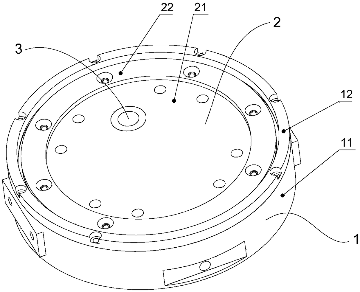
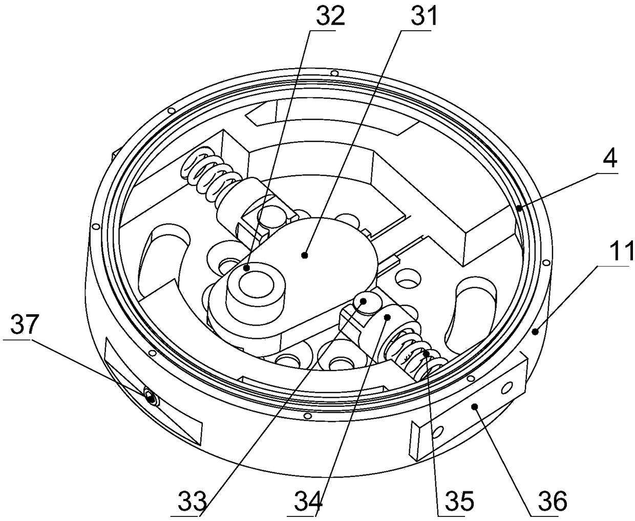
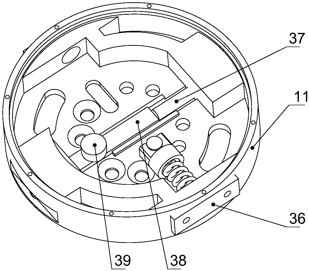
[0033] Such as Figure 1 to Figure 3 As shown, this embodiment discloses a robot joint variable stiffness module based on a cam-type lever structure. The variable stiffness module mainly includes an input part 1, an output part 2, and a stiffness adjustment part 3. The output part 2 is provided in the input part 1. A bearing 4 is provided between the input part 1 and the output part 2 to withstand the non-torque load of the entire module and to enable the input part 1 and the output part 2 to rotate relatively.

[0034] Specifically, the input part 1 includes a housing 11 and a housing bearing retaining ring 12. The housing bearing retaining ring 12 is arranged on the housing 11 and is fixedly connected with the housing 11. The casing 11 is provided with a guide groove for restraining the compression spring 35 and the rigidity adjusting fulcrum 39. The guide groove is located at the bottom of the housing 11; the housing 11 is provided with necessary installa...

Example Embodiment

[0043] Example 2:

[0044] Figure 1 to Figure 3 As shown, this embodiment discloses a robot joint variable stiffness module based on a cam-type lever structure, which includes an input part 1, an output part 2 and a stiffness adjustment part 3. The rigidity adjustment part 3 includes a compression spring 35, a cam lever 31 and a rigidity adjustment fulcrum 39; the cam lever 31 rotates around the rigidity adjustment fulcrum 39, and one end thereof is matched with the output disk 21 and the other end is matched with the compression spring 35. When an external load is loaded on the output disc 21 of the variable stiffness module, it is transmitted to the compression spring 35 through the action of the cam lever 31. At this time, the compression spring is compressed under the action of external force and the cam lever 31 is deflected by an angle. Due to the change of the angle of the cam lever 31, the output disk 21 is eventually deflected. This process is equivalent to when the v...


PUM


Abstract

The invention discloses a robot joint variable rigidity module based on a cam type lever structure. The robot joint variable rigidity module comprises an input part, an output part and a rigidity adjusting part. The rigidity adjusting part comprises pressure springs, a cam type lever and a rigidity adjusting supporting point. The cam type lever rotates around the rigidity adjusting supporting point, one end of the cam type lever cooperates with the output part, and the other end of the cam type lever cooperates with the pressure springs. A bearing is arranged between the input part and the output part so as to bear non-torque loads of the whole module and enable the input part and the output part to relatively rotate. When the output part of the variable rigidity module bears outer instantloads, the loads are transmitted to the pressure springs through the cam type lever to be absorbed, and therefore outer impacts are reduced, and flexible drive output is achieved; and meanwhile the robustness and operation stability of a robot are improved. The robot joint variable rigidity module is compact in structure and low in cost and is integrated into a module, and therefore the robot joint variable rigidity module can be conveniently applied to various kinds of interactive equipment, especially, flexible robot joints. The robot joint variable rigidity module further has the advantages of being convenient to operate and easy to implement.

Description

technical field [0001] The invention relates to the field of robots, in particular to a robot joint variable stiffness module based on a cam-type lever structure. Background technique [0002] With the rapid development of modern industrial technology, the scope of application of robots has expanded dramatically, and human-machine collaboration has become increasingly close. With the continuous deepening of human-computer interaction, the working environment of the robot has become complex and has great uncertainty. It may collide with objects and people in the surrounding environment at any time, which poses a high challenge to the safety of the robot. Require. For example, the robot needs to dynamically adjust the joint stiffness and the active / passive flexibility of the robot joint according to the changes of the external environment and its own load. Therefore, it has become a technical difficulty in the field of collaborative robots to add a high-performance, compact ...

Claims


Application Information

Patent Timeline
IPC IPC(8): B25J17/02
CPCB25J17/0208
Inventor 朱海飞钟玉赵波谷世超管贻生
Owner GUANGDONG UNIV OF TECH
Why Eureka
Try Eureka