Foundation pile torsional wave low strain detection method capable of eliminating bending and longitudinal interference

A detection method and torsional wave technology, applied in basic structure engineering, basic structure testing, construction, etc., can solve problems affecting the application and interference of torsional waves, achieve low vibration excitation requirements, accurate and reliable results, and improve accuracy The effect of reliability

Inactive Publication Date: 2019-03-15
CHINA ACAD OF BUILDING RES
View PDF3 Cites 0 Cited by
  • Summary
  • Abstract
  • Description
  • Claims
  • Application Information

AI Technical Summary

Problems solved by technology

However, the torsional wave signal acquisition is seriously interfered by other vibrations, which seriously affects the application of torsional wave

Method used


Image

  • Foundation pile torsional wave low strain detection method capable of eliminating bending and longitudinal interference
  • Foundation pile torsional wave low strain detection method capable of eliminating bending and longitudinal interference

Examples


Embodiment 1

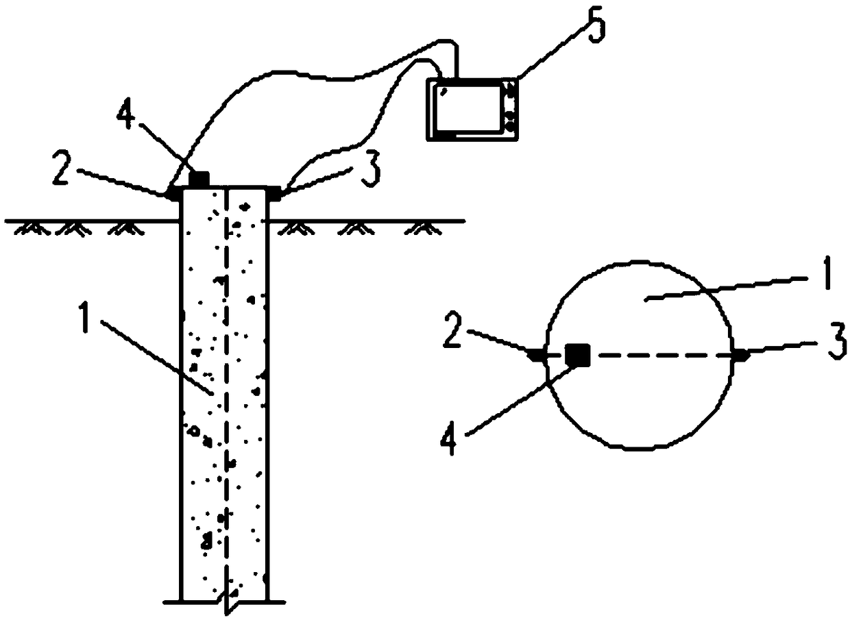
[0029] The invention provides a torsional wave low-strain detection method for foundation piles capable of eliminating bending and longitudinal interference. figure 1 A schematic diagram of the installation structure of the equipment used in this method is given, in which: the foundation pile 1, the first sensor 2, the second sensor 3, the excitation block 4, the dual-channel data acquisition instrument 5, the excitation block 4 can be installed on the pile The top or pile side, when installed on the top of the pile, it needs to be installed on the pile top plane close to the pile side, figure 1 What is given in is that the vibration block 4 is installed on the top of the pile and close to the side of the pile. The sensors can also be installed on the top of the pile or on the side of the pile. The two sensors should be symmetrical to the geometric center of the foundation pile. When the two sensors are installed on the top of the pile, they should also be installed on the pil...

Embodiment 2

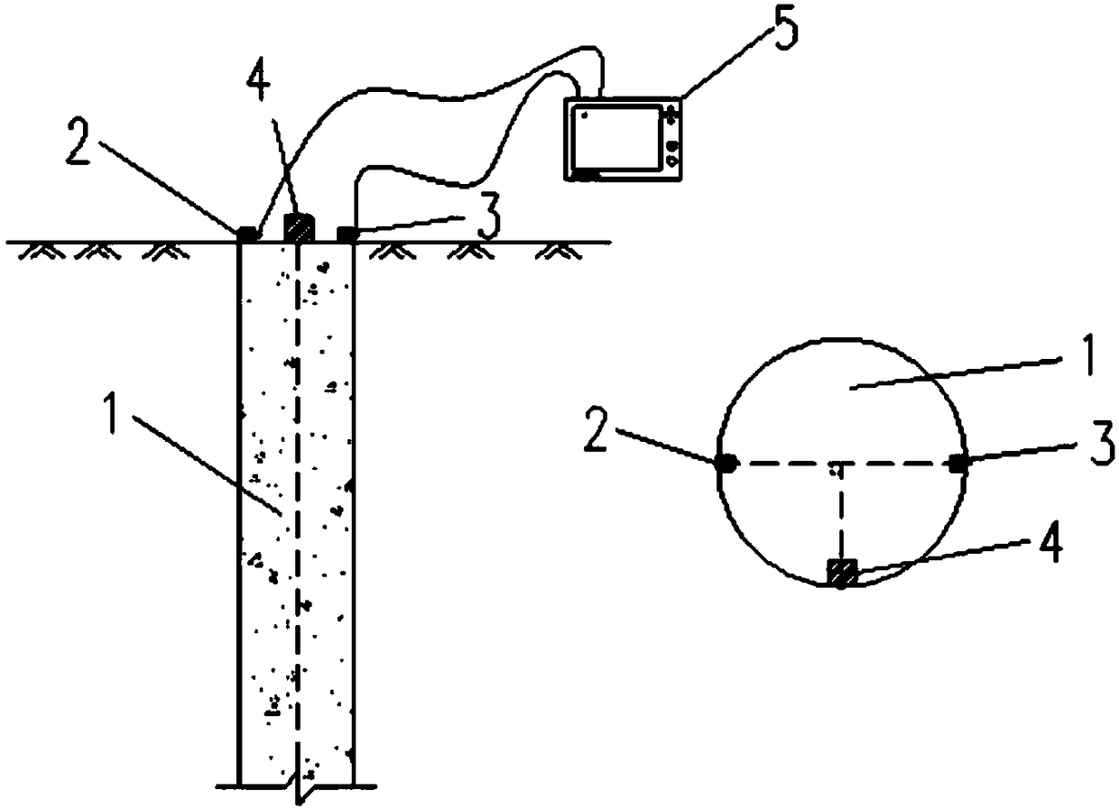
[0054] Due to the limited range and accuracy of the signal acquisition system, when the bending vibration is strong, in order to increase the proportion of the torsional wave signal and reduce the test error, it is sometimes necessary to set the angle between the sensor and the excitation block to 90°. figure 2 Another embodiment of the method is given, wherein: foundation pile 1, first sensor 2, second sensor 3, excitation block 4, dual-channel data acquisition instrument 5, excitation block 4 can be installed on the pile top or pile side, figure 2 What is given in is that the vibration block 4 is installed on the top of the pile and close to the side of the pile. The sensors can also be installed on the top of the pile or on the side of the pile. The two sensors should be symmetrical to the geometric center of the foundation pile. When the two sensors are installed on the top of the pile, they should also be installed on the pile top plane close to the pile side. figure ...


PUM


Abstract

The invention provides a foundation pile torsional wave low strain detection method capable of eliminating bending and longitudinal interference. The pile top or the pile side is symmetrically provided with two sensors relative to the geometric center of a foundation pile, and an excitation block is installed on the pile top or the pile side, and the circle center angle between the excitation block and the two sensors is 0 degree, 90 degrees or 180 degrees. Two sensors are used to collect the vibration signal. According to the wave theory of the one-dimensional rod and the different characteristics of the torsional wave, the longitudinal wave and the bending wave, the longitudinal wave interference and the bending wave interference are removed by the calculation and analysis, and only thetorsional wave signal is retained in the signal. The method has simple principle, simple operation, low requirements for excitation, improved on-site operation efficiency, simple acquisition equipment, accurate and reliable results, and strong engineering application and promotion prospects.

Description

technical field [0001] The invention relates to the field of engineering detection, in particular to a method for detecting the integrity of foundation piles. Background technique [0002] Pile foundation integrity detection is of great significance for ensuring the quality of foundation piles such as buildings, bridges and ports. When it is necessary to understand the quality of the project, it is necessary to detect the integrity (defects) of foundation piles. At present, the most common method used to detect the integrity of foundation piles is the low-strain method, which uses longitudinal waves or torsional waves for detection, and uses small hammers or force rods to excite the pile foundations to apply a concentrated force along the pile length direction to the foundation piles. Or force couple, use the velocity or acceleration sensor to measure the longitudinal or horizontal velocity curve of the pile body, and use the wave theory of the rod to identify and analyze th...

Claims


Application Information

Patent Timeline
Patent Type & Authority Applications(China)
IPC IPC(8): E02D33/00
CPCE02D33/00E02D2600/10
Inventor 徐教宇
Owner CHINA ACAD OF BUILDING RES
Why Eureka
Try Eureka