A horizontally opposed engine with coaxially arranged cylinders

A coaxial arrangement, horizontally opposed technology, applied in the direction of machines/engines, mechanical equipment, etc., can solve the problems of high manufacturing cost and maintenance cost of horizontally opposed engines, reduced service life of pistons and cylinders, uneven wear of cylinder walls, etc. , to improve energy utilization, prolong service life and eliminate uneven wear

Active Publication Date: 2021-04-06
李杰 +1
View PDF4 Cites 0 Cited by
  • Summary
  • Abstract
  • Description
  • Claims
  • Application Information

AI Technical Summary

Problems solved by technology

[0004] At the same time, there are many disadvantages in the horizontally opposed arrangement of the cylinders: 1. Like all engines of the crank-and-link mechanism, during the operation of the horizontally opposed engine, the reaction force of the crankshaft to the piston makes the piston have alternating pressure on the inner wall of the cylinder, which wastes At the same time, the service life of the piston and cylinder is reduced; 2. The horizontal arrangement of the cylinder causes the direction of gravity on the piston to be perpendicular to its own axis, so the friction between the side of the piston near the bottom of the engine and the cylinder wall is much greater than that of the other side. side, which causes uneven wear on the cylinder walls
These features make boxer engines expensive to manufacture and maintain

Method used


Image

  • A horizontally opposed engine with coaxially arranged cylinders
  • A horizontally opposed engine with coaxially arranged cylinders
  • A horizontally opposed engine with coaxially arranged cylinders

Examples


Embodiment Construction

[0022] The present invention will be further described in detail below in conjunction with the accompanying drawings and embodiments.

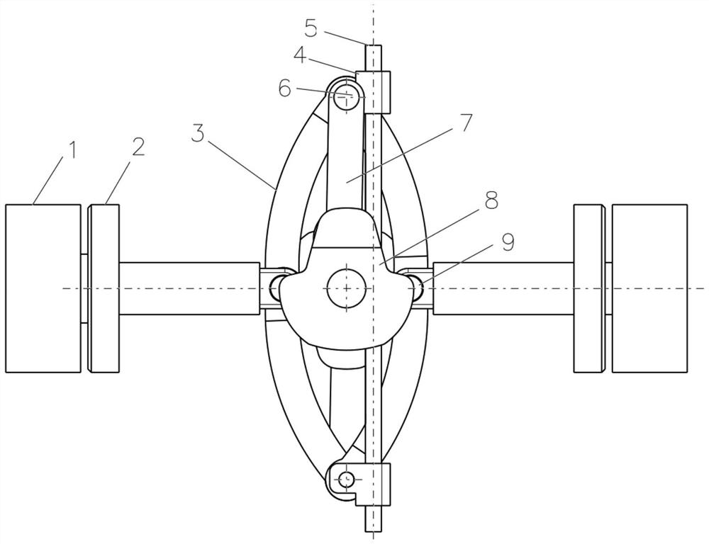
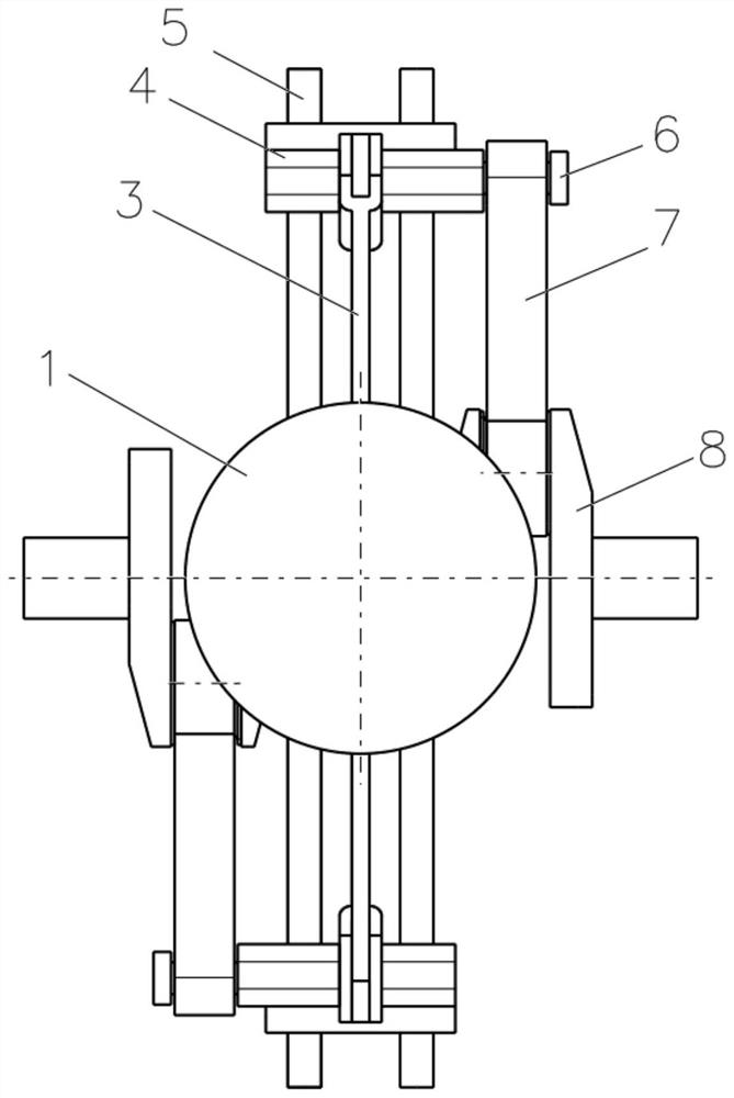
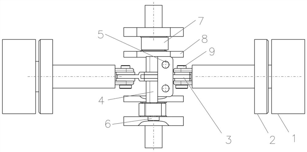
[0023] See attached Figure 1-3 , this embodiment provides a horizontally opposed engine with cylinders coaxially arranged, including: a piston 1, a piston connecting rod assembly 3, a piston connecting rod guide rod 5, a crankshaft connecting rod 7 and a crankshaft 8;

[0024] See attached Figure 4 , the piston connecting rod assembly 3 is an annular structure composed of arc-shaped first connecting rod 31, second connecting rod 32, third connecting rod 33, and fourth connecting rod 34 with the same structure; since the four connecting rods have the same structure , then the piston-connecting rod assembly 3 is symmetrical up and down, left and right.

[0025] Wherein the two connection points in the vertical direction of the piston connecting rod assembly 3 are respectively provided with a piston connecting rod guide block 4, and the two c...


PUM


Abstract

The invention relates to the technical field of engines, in particular to a horizontally opposed engine. A horizontally opposed engine with cylinders coaxially arranged, the technical proposal of which is: a piston connecting rod guide block is respectively connected to a group of opposite hinge points in the piston connecting rod assembly; the number of pistons is two, respectively located in the horizontal In the opposite cylinder; the ends of the two pistons are respectively connected with another set of opposite hinge points in the piston connecting rod assembly; the piston connecting rod guide rods are two straight rods arranged in parallel and fixedly connected with the engine housing; Each piston connecting rod guide block is sleeved on the piston connecting rod guide rod; each piston connecting rod guide block is connected with a crankshaft through a crankshaft connecting rod. The invention eliminates the vibration of the traditional engine caused by the incomplete symmetry of the cylinder by arranging the opposed piston groups coaxially, improves the energy utilization rate of the engine, reduces the engine vibration, and prolongs the service life of the cylinder and the piston.

Description

technical field [0001] The invention relates to the technical field of engines, in particular to a horizontally opposed engine. Background technique [0002] Crank-and-connecting rod engines currently in use are generally divided into one-way in-line type, V-shaped arrangement type and horizontally opposed type. The horizontally opposed engine is a special V-type engine with an angle of 180° between the cylinders on both sides of the crankshaft. [0003] Compared with the traditional one-way in-line engine, the advantages of the horizontally opposed engine are mainly reflected in: 1. The height of the engine itself is low, which is beneficial to lower the center of gravity of the vehicle and enhance the driving stability of the vehicle; 2. The vibration of the engine itself is small, which greatly reduces the 3. The engine speed is greatly increased, which is conducive to exerting the maximum power. [0004] At the same time, there are many disadvantages in the horizontally...

Claims


Application Information

Patent Timeline
Patent Type & Authority Patents(China)
IPC IPC(8): F02B75/24F02B75/32
CPCF02B75/24F02B75/32
Inventor 李京泽刘非
Owner 李杰
Why Eureka
Try Eureka