Conversion mechanism of combined rack and combined crankshaft

A combined crankshaft and conversion mechanism technology, applied to crankshafts, mechanical equipment, machines/engines, etc., can solve problems such as low efficiency, affecting engine output power, and increasing lateral friction between the piston and cylinder wall

Pending Publication Date: 2020-10-27
安里千
View PDF0 Cites 0 Cited by
  • Summary
  • Abstract
  • Description
  • Claims
  • Application Information

AI Technical Summary

Problems solved by technology

[0002] At present, piston internal combustion engines (engines) generally use a crankshaft-connecting rod mechanism to convert the reciprocating linear motion of the piston into circular motion. However, there are still some insurmountable defects in the crankshaft-connecting rod mechanism, which need to be further improved and optimized:
[0003] 1. In the traditional crankshaft-connecting-rod mechanism, the gas explosion force acting on the piston in the cylinder can only be transformed into the tangential force of the crank that drives the crankshaft after multiple decompositions. Theoretical analysis and practical application tests show that when acting on the piston When the maximum gas explosive force reaches the maximum value, only about 20% of the maximum gas explosive force is decomposed into a tangential force perpendicular to the crank radius, that is, only about one-fifth of the maximum gas explosive force drives the crank and crankshaft to rotate and output torque. Therefore, the efficiency of converting the reciprocating linear motion of the piston into cir

Method used


Image

  • Conversion mechanism of combined rack and combined crankshaft
  • Conversion mechanism of combined rack and combined crankshaft
  • Conversion mechanism of combined rack and combined crankshaft

Examples


Embodiment Construction

[0049] The specific implementation of a combined rack-combined crankshaft conversion mechanism provided by the present invention will be described in detail below with reference to the accompanying drawings.

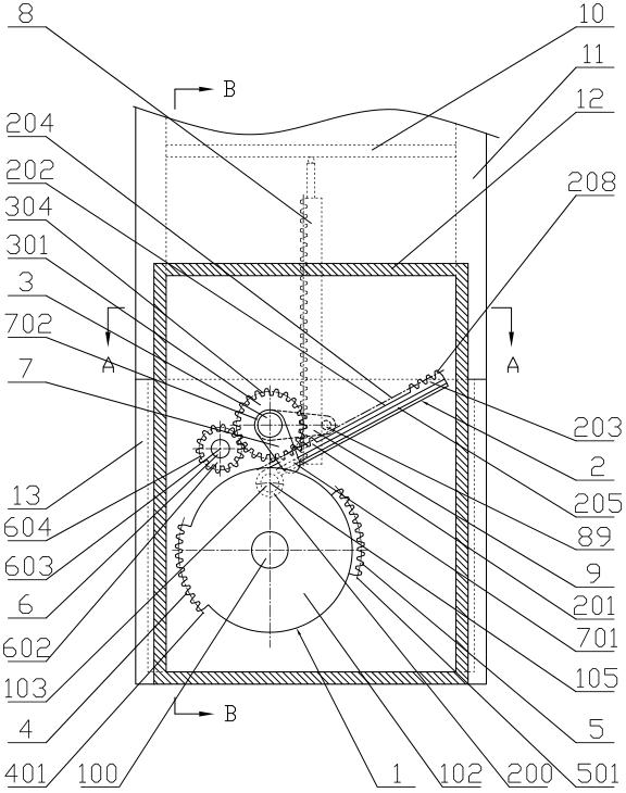
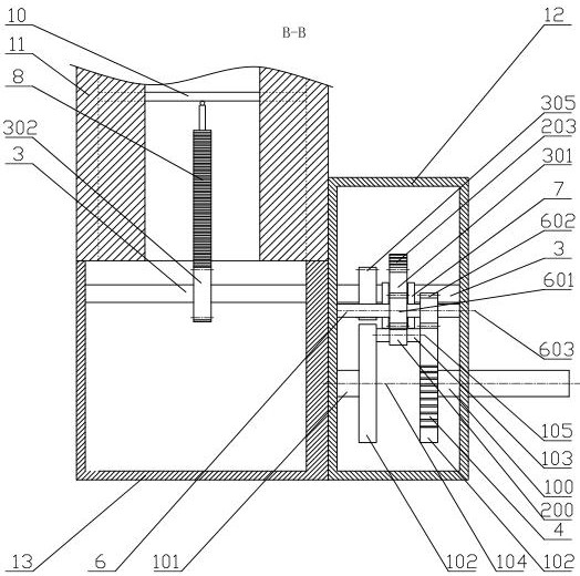
[0050] Such as figure 1 , 2 , 3, the main components of the first embodiment of a combined rack-combined crankshaft conversion mechanism of the present invention include a front main journal 100 and a rear main journal 101, two cranks 102 and its front fan ring 4 and The combined crankshaft 1 composed of the rear fan gear ring 5 and the connecting rod journal 103, the transmission shaft 3 with the main gear 301 and the pinion gear 305, the steering wheel shaft 6 with the steering gear 601 and the auxiliary gear 602, and the toothless middle section The rack 202 and the combined rack 2 formed by the first rack 201 and the last rack 203 at both ends are characterized in that the front main journal 100 and the rear main journal 101 as well as the drive shaft 3 and the stee...


PUM


Abstract

The invention discloses a conversion mechanism of a combined rack and a combined crankshaft. A front main shaft neck and a rear main shaft neck of the combined crankshaft, a transmission shaft and a steering wheel shaft are mounted on the box wall of a crankcase, a steering gear on the steering wheel shaft meshed with a main gear on the transmission shaft drives an auxiliary gear to be alternatelymeshed with a front sector gear ring of the combined crankshaft, an auxiliary gear on the transmission shaft is alternately meshed with a rear sector gear ring of the combined crankshaft, a connecting rod ring at one end part of the combined rack is installed on a connecting rod journal, and a first section rack and a last section rack of the combined rack are alternately meshed with the main gear of the transmission shaft; short guide rails of two guide plates mounted on the transmission shaft are respectively arranged in limiting grooves on the two sides of the combined rack; and limiting flat rods on the two sides of a driving rack meshed with a driving gear on the transmission shaft are respectively installed on the positions, located on the two sides of the driving gear, of the transmission shaft, the part, located between the two limiting flat rods, of a rotating shaft is arranged on the back surface of the driving rack, and each driving rack is hinged to a piston to form an engine group, with only one set of combined crankshaft, of multiple cylinders.

Description

technical field [0001] The invention relates to a mechanical device for converting the reciprocating linear motion of the piston into the circular motion of the crankshaft, in particular to a combined rack-combined crankshaft conversion mechanism to replace the existing crankshaft (handle)-connecting rod conversion mechanism. Background technique [0002] At present, piston internal combustion engines (engines) generally use a crankshaft-connecting rod mechanism to convert the reciprocating linear motion of the piston into circular motion. However, there are still some insurmountable defects in the crankshaft-connecting rod mechanism, which need to be further improved and optimized: [0003] 1. In the traditional crankshaft-connecting-rod mechanism, the gas explosion force acting on the piston in the cylinder can only be transformed into the tangential force of the crank that drives the crankshaft after multiple decompositions. Theoretical analysis and practical application t...

Claims


Application Information

Patent Timeline
IPC IPC(8): F16H37/12F16C3/06F02B75/32F04B17/03F04B35/04F04B39/00
CPCF02B75/32F04B17/03F04B35/04F04B39/00F16C3/06F16H37/124
Inventor 安里千刘庆王聪
Owner 安里千
Why Eureka
Try Eureka