Crankshaft-free engine transmission device

A transmission and engine technology, applied in the direction of machines/engines, mechanical equipment, etc., can solve problems such as increasing uneven friction and impact, affecting engine output power, large engine vibration and noise, etc., to reduce momentum loss and power transmission Reasonable conversion of movement mode and improvement of output torque

Inactive Publication Date: 2016-02-24
安里千
View PDF9 Cites 0 Cited by
  • Summary
  • Abstract
  • Description
  • Claims
  • Application Information

AI Technical Summary

Problems solved by technology

[0006] 3. In the crankshaft connecting rod mechanism, the unbalanced rotary mass and rotary motion caused by the swing of the connecting rod cause the inertial force, which makes the piston, the cylinder wall and the rotating contact surface produce alternating impact force, which increases the uneven friction and impact between the various components, not only Affect the output power of the engine, and make the engine generate greater vibration and noise

Method used


Image

  • Crankshaft-free engine transmission device
  • Crankshaft-free engine transmission device
  • Crankshaft-free engine transmission device

Examples


Embodiment Construction

[0046] The specific implementation of the crankshaftless engine transmission of the present invention will be described in detail below with reference to the accompanying drawings.

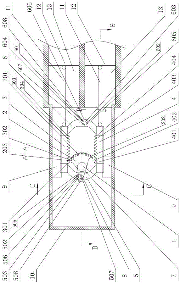
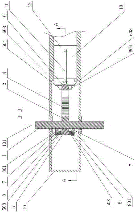
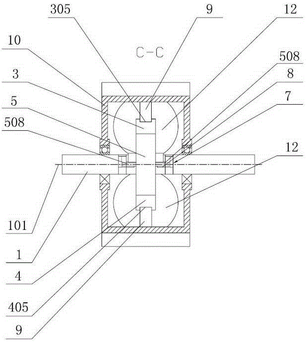
[0047] The first embodiment of the crankshaftless engine transmission of the present invention comprises: figure 1 As shown in -3, the cylindrical surface of the main shaft 1 in the housing 10 is coaxially rigidly connected with the sector gear 2, and the sector gear 2 is placed on the rack 3 and the rack 4, and the rack connecting plate 5 and the rack connecting plate 6. In the rack frame, the teeth of the sector gear 2 can alternately mesh with the rack 3 and the rack 4; one end of the two rotating arms 7 with the same shape is rigidly connected with the main shaft 1 cylinder on both sides of the sector gear 2, and the two The shapes of the two rotating arms 7 are the same and symmetrical about the longitudinal middle section of the sector gear 2. The main shaft 1, the sector gear 2 and the two ...


PUM


Abstract

A crankshaft-free engine transmission device is characterized in that a sector gear 2 on a main shaft 1 in a housing 10 is positioned in a frame which is composed of racks 3 and 4 and rack connecting plates 5 and 6, wherein rotating arms 7 are arranged at two sides of the sector gear 2; circular arc shaped grooves 701 and turning grooves 702 are correspondingly formed in opposite inner side surfaces of the two rotating arms 7; driving pins 8 are arranged on the edges of the two circular arc shaped grooves 701 and the turning grooves 702; driving grooves 501 and 601 and guide grooves 502 and 602 are correspondingly formed in two side surfaces of the rack connecting plates 5 and 6; turning pins 508 and 608 are mounted on the outer edges of the driving grooves 501 and 601; the racks 3 and 4 are correspondingly positioned on guide rails 9 on the sidewalls of the housing 10; the end parts of the racks 3 and 4 are connected to pistons 12 in air cylinders 13 through connecting rods 11 to form a single-cylinder or multi-cylinder engine set. With the adoption of the device, the mechanical conversion efficiency of an engine can be greatly improved, and the lateral frictional force between the pistons and the cylinder walls can be completely removed.

Description

technical field [0001] The invention relates to a mutual conversion mechanism of reciprocating linear motion and circular motion, in particular to an engine transmission device replacing the crankshaft connecting rod mechanism, which improves the mutual conversion efficiency of the engine's reciprocating linear motion and rotary motion. Background technique [0002] In mechanical engineering, such as piston engines, compressors and other machines that need to convert linear reciprocating motion and circular motion, crankshaft (crank) connecting rod conversion mechanism is generally used at present. [0003] The design and manufacture of the traditional crankshaft (handle) linkage mechanism has been very perfect, but there are inherent defects in both theoretical analysis and practical application: [0004] 1. In the crankshaft (handle) connecting rod mechanism, the gas pressure acting on the piston is decomposed into the force along the axis of the connecting rod and the si...

Claims


Application Information

Patent Timeline
Patent Type & Authority Applications(China)
IPC IPC(8): F02B75/32
CPCF02B75/32
Inventor 安里千刘庆毛灵涛刘升贵任珉
Owner 安里千
Why Eureka
Try Eureka