Waste heat reuse control system

A control system and central control technology, applied in the direction of comprehensive factory control, comprehensive factory control, electrical program control, etc., can solve the problems of lack of scientific and effective methods of utilization, waste heat loss, non-replicability, etc., and achieve excellent reproducible operation. flexibility, lower production costs, and the effect of wide versatility

Inactive Publication Date: 2016-03-30
天津凯斯威森科技发展有限公司
View PDF5 Cites 0 Cited by
  • Summary
  • Abstract
  • Description
  • Claims
  • Application Information

AI Technical Summary

Problems solved by technology

However, the utilization methods of these enterprises lack scientific and effective methods. In practical applications, there is still a considerable loss of waste heat, resulting in a waste of resources and energy.
Moreover, the implementation methods of a single enterprise have their own specific environmental requirements and limitations, and are non-replicable and non-promotable.
[0003] With the increase of energy costs year by year, the reuse of waste heat has gradually been valued by enterprises, but there is still a lack of scientific and efficient waste heat reuse systems to reduce energy costs of enterprises and at the same time meet the requirements of energy saving and emission reduction

Method used


Image

  • Waste heat reuse control system
  • Waste heat reuse control system
  • Waste heat reuse control system

Examples


Embodiment Construction

[0034] The specific implementation manners of the present invention will be briefly described below in conjunction with the accompanying drawings.

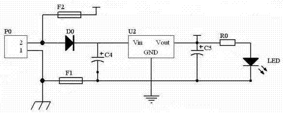
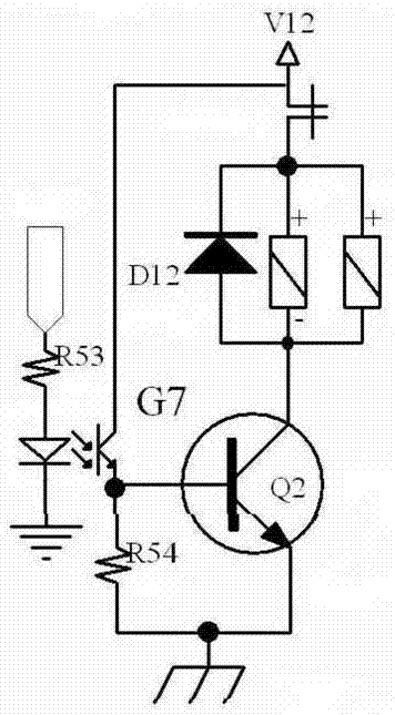
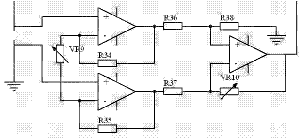
[0035] Such as figure 1 , figure 2 , image 3 , Figure 4 , Figure 5 , Image 6 , Figure 7 , Figure 8 , Figure 9 , Figure 10 , Figure 11 , Figure 12 , Figure 13 , Figure 14 As shown, the waste heat reuse control system is mainly composed of a regulated power supply circuit 1, a relay state drive circuit 2, a pressure sensor constant current power supply circuit 3, a pressure signal amplifying circuit 4, a temperature signal input port 5, a temperature signal amplifying circuit 6, and a central Controller working oscillation circuit 7, valve switch state display circuit 8, central control chip circuit 9, three-way valve state control circuit 10, reset circuit 11, actuator control circuit 12, A / D conversion voltage reference circuit 13. The relay state drive circuit 2 is electrically connected to the pressure ...


PUM


Abstract

The invention aims to solve the problem of providing a scientific and efficient waste heat reutilization control system. The technical solution is that the waste heat utilization control system is mainly composed of a regulated power supply circuit, a relay state driving circuit, a pressure sensor constant-current power supply circuit, a pressure signal amplification circuit, a temperature signal input port, a temperature signal amplification circuit, a central controller operation oscillating circuit, a valve on-off state display circuit, a central control chip circuit, a three-way valve state control circuit, a reset circuit, an actuator control circuit and an A / D conversion voltage reference circuit; and the relay state driving circuit is electrically connected with the pressure signal amplification circuit, and the pressure sensor constant-current power supply circuit is electrically connected with the pressure signal amplification circuit. The waste heat reutilization control system has the beneficial effects that waste heat can be converted into other utilizable resources more efficiently and more reasonably, thereby achieving the purposes of saving energy, reducing emission, reducing the production cost, and increasing profits.

Description

technical field [0001] The invention relates to the technical field of energy reuse, in particular to a waste heat reuse control system. Background technique [0002] In the process of industrial production, due to machine friction, cooling and other reasons, a large amount of waste heat will be generated. In the early days, the waste heat will be directly discharged, and in the near future, some enterprises will use the waste heat for heating and other environments of the enterprise. However, the utilization methods of these enterprises lack scientific and effective methods, and in practical applications, there is still a considerable loss of waste heat, resulting in a waste of resources and energy. Moreover, the implementation methods of a single enterprise have their own specific environmental requirements and limitations, and are non-replicable and non-promotable. [0003] With the increase of energy cost year by year, the reuse of waste heat has gradually been valued ...

Claims


Application Information

Patent Timeline
Patent Type & Authority Patents(China)
IPC IPC(8): G05B19/418
CPCY02P90/02
Inventor 张炳祥姜印平孙从一王智涛
Owner 天津凯斯威森科技发展有限公司
Why Eureka
Try Eureka