Star sensor

A technology of star sensors and area array detectors, applied in the field of star sensors, can solve problems such as increased volume, weight and power consumption, increased complexity and cycle, and is not conducive to the optimal configuration of flight platform loads to achieve high-precision positioning Effect

Active Publication Date: 2019-03-15
CHANGCHUN INST OF OPTICS FINE MECHANICS & PHYSICS CHINESE ACAD OF SCI
View PDF15 Cites 6 Cited by
  • Summary
  • Abstract
  • Description
  • Claims
  • Application Information

AI Technical Summary

Problems solved by technology

The registration process adds complexity and cycle time to manufacturing
In addition, the volume, weight and power consumption of the combination of the two devices are also doubled, which is not conducive to the optimal configuration of the flight platform load

Method used


Image

  • Star sensor
  • Star sensor
  • Star sensor

Examples


Embodiment Construction

[0025] The following will clearly and completely describe the technical solutions in the embodiments of the present invention with reference to the accompanying drawings in the embodiments of the present invention. Obviously, the described embodiments are only some, not all, embodiments of the present invention. Based on the embodiments of the present invention, all other embodiments obtained by persons of ordinary skill in the art without making creative efforts belong to the protection scope of the present invention.

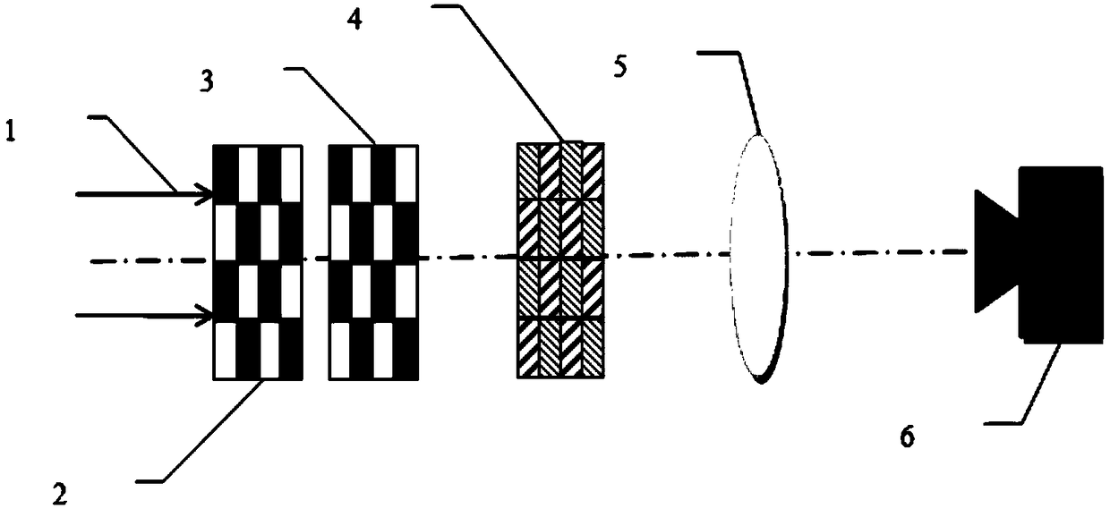
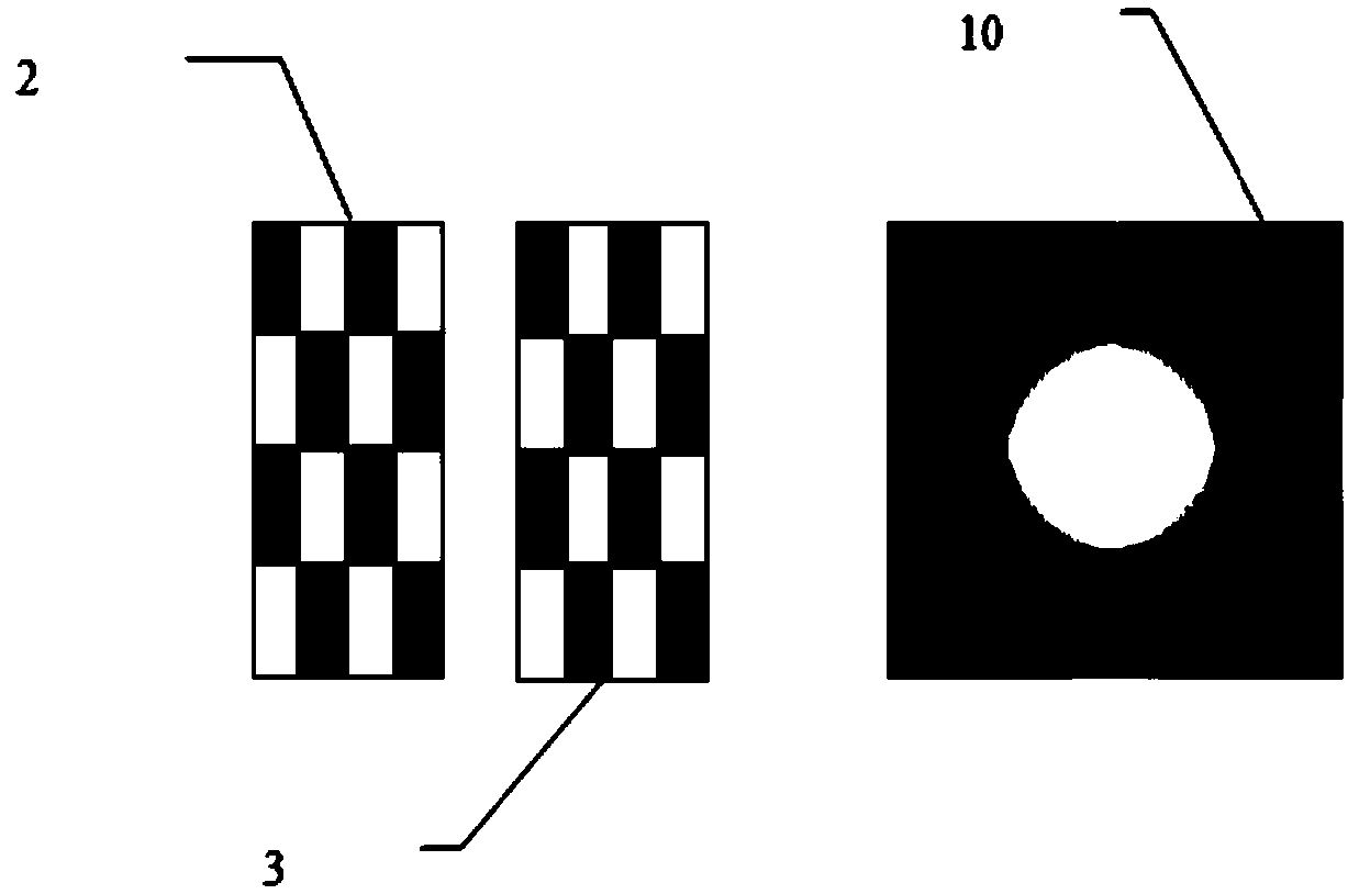
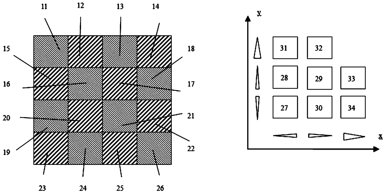
[0026] see figure 1 , is a structural schematic diagram of the star sensor provided by the embodiment of the present invention, including: a front checkerboard grating 2, a rear checkerboard grating 3, a checkerboard wedge array 4, a converging optical system 5 and an area array detector 6, so The front checkerboard grating 2 and the rear checkerboard grating 3 form a shearing interferometer.

[0027] The specific solution of each component will be described ...


PUM


Abstract

The invention provides a star sensor. The star sensor comprises a front checkerboard-shaped optical grating, a rear checkerboard-shaped optical grating, a checkerboard-shaped optical wedge array, a converging optical system and an area array detector, wherein total input light consisting of target light and sky background light enters a shearing interferometer consisting of the front checkerboard-shaped optical grating and the rear checkerboard-shaped optical grating, a two-dimensional interference fringe with a full cycle is formed through the adjustment of the relative angle between the front checkerboard-shaped optical grating and the rear checkerboard-shaped optical grating, the checkerboard-shaped optical wedge array performs two-dimensional light splitting on the incident two-dimensional interference fringe, split light beams formed after the two-dimensional light splitting of the checkerboard-shaped optical wedge array run through the converging optical system and then are gathered to a target surface of the area array detector, and two-dimensional phase information of the two-dimensional interference fringe is acquired according to the spot intensity of the target surface and a corresponding phase extracting algorithm, so that two-dimensional synchronous high-precision positioning is achieved.

Description

technical field [0001] The invention relates to the technical field of optical tracking equipment, in particular to a star sensor. Background technique [0002] Optical tracking technology is a general-purpose technology that is widely used. It can be used for precise pointing of laser beams, position and attitude maintenance of flying platforms, high-precision tracking and aiming of large-aperture photoelectric telescopes, etc. A star tracking device, usually called a star sensor, obtains the position and attitude information of an aircraft (satellite, etc.) by detecting the star field distribution in a large area. [0003] Traditional star sensors generally use optical lenses to converge starlight to the target surface of the array detector, and achieve high-precision positioning of the target through methods such as telephoto, small pixels, and sub-pixel centroid extraction based on interpolation. The currently achievable accuracy is about 1 / 10 to 1 / 50 of a pixel. For ...

Claims


Application Information

Patent Timeline
Patent Type & Authority Applications(China)
IPC IPC(8): G01C21/02
CPCG01C21/025
Inventor 董磊王建立李洪文
Owner CHANGCHUN INST OF OPTICS FINE MECHANICS & PHYSICS CHINESE ACAD OF SCI
Why Eureka
Try Eureka