
Novel rapid bidirectional reflection distribution function testing system and method

A technology of bidirectional reflection distribution and testing system, which is applied in the field of new bidirectional reflection distribution function rapid testing system, can solve the problems of increased repetition error of testing system, small receiving area of ​​photodetector, signal error, etc.

Pending Publication Date: 2019-03-15
BEIJING UNIV OF TECH +1
View PDF7 Cites 6 Cited by
  • Summary
  • Abstract
  • Description
  • Claims
  • Application Information

AI Technical Summary

Problems solved by technology

For example, the patent "A New Bidirectional Reflection Distribution Function Measuring Device", patent number: 201210075733.2, but the limitation of this method is that the receiving surface of the photodetector is small, and the reflection beam spread angle is required to be small, which means that only the mirror surface can be used. Scattering on the surface of the object, if it is a rough surface, it is difficult to realize the collection of each optical signal scattered to the entire hemispherical space, resulting in signal errors
[0007] It can be seen from the above that the current problems of the device for measuring the two-way reflection distribution of the surface mainly include: 1. It is difficult to measure the reflection data in the entire 2π hemisphere space online; 2. The test accuracy is poor, and the repeat error of the test system increases; 3. The manufacturing process of the system complex

Method used


Image

  • Novel rapid bidirectional reflection distribution function testing system and method
  • Novel rapid bidirectional reflection distribution function testing system and method
  • Novel rapid bidirectional reflection distribution function testing system and method

Examples


Embodiment Construction

[0037] In order to make the purpose, technical solutions and advantages of the embodiments of the present invention clearer, the technical solutions in the embodiments of the present invention will be clearly and completely described below in conjunction with the drawings in the embodiments of the present invention. Obviously, the described embodiments It is a part of embodiments of the present invention, but not all embodiments. Based on the embodiments of the present invention, all other embodiments obtained by persons of ordinary skill in the art without making creative efforts belong to the protection scope of the present invention.

[0038] In the description of the present invention, it should be noted that the terms "center", "upper", "lower", "left", "right", "vertical", "horizontal", "inner", "outer" etc. The indicated orientation or positional relationship is based on the orientation or positional relationship shown in the drawings, and is only for the convenience of...


PUM


Abstract

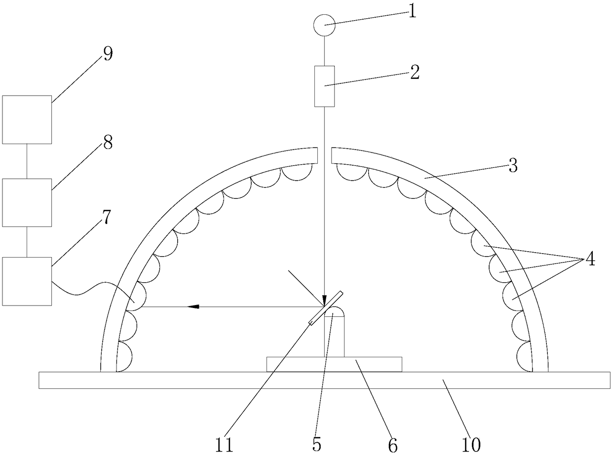
The invention discloses a novel rapid bidirectional reflection distribution function testing system and method. An optical aperture is formed in the top of a hemispherical testing darkroom; a testinglight source is arranged just above the optical aperture; multiple photoelectric detectors are tightly arranged on the inner spherical surface of the hemispherical testing darkroom; all the photoelectric detectors are connected with a signal processing system; a four-dimensional working turntable is arranged in the hemispherical testing darkroom; a to-be-tested sample is arranged on the four-dimensional working turntable by virtue of a sample supporting component; the four-dimensional working turntable drives the horizontal plane and the vertical plane of the to-be-tested sample to rotate; after light beams of the testing light source come into the to-be-tested sample via the optical aperture after collimation; incident light are scattered via the to-be-tested sample, the scattered light signal is received by the photoelectric detectors, the photoelectric detectors output signals to the signal processing system to process so as to obtain the bidirectional reflection distribution function of the to-be-tested sample. According to the system and method disclosed by the invention, rapid measurement of the bidirectional reflection distribution function of the sample in a 2Pi hemispherical space range can be realized, and the measurement accuracy is high.

Description

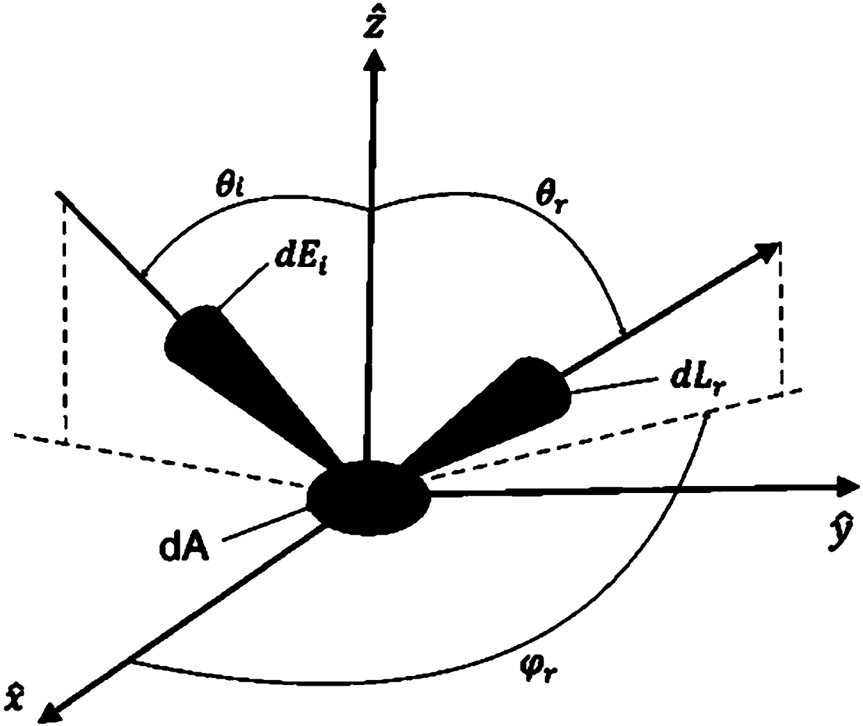
technical field [0001] The invention relates to the field of optical technology, in particular to a novel rapid test system and method for bidirectional reflection distribution functions. Background technique [0002] The bidirectional reflectance distribution function (BRDF) was proposed by the American scholar Nicodemus in 1970. It represents the reflection characteristics of the surface of an object at any reflection angle under different incident conditions, such as figure 1 shown. Bidirectional reflectance distribution function is an important function to describe the diffuse reflection characteristics of materials, which is the ratio of the reflected brightness of light radiation to the incident irradiance; its mathematical expression is: [0003] [0004] where θ i , is the incident angle and azimuth angle of the incident light, θ r , is the reflection angle and azimuth angle of the reflected light. L r is the test surface element dA after irradiation in θ...

Claims


Application Information

Patent Timeline
Patent Type & Authority Applications(China)
IPC IPC(8): G01N21/47
CPCG01N21/4738G01N2021/4711
Inventor 代京京王智勇刘豫颖赵思思张景豪
Owner BEIJING UNIV OF TECH
Learn More