Ventilation device for venting a space, in particular an engine room of a vehicle

A technology for ventilation device and engine room, applied in the direction of engine cooling, power plant, engine components, etc., can solve problems such as hindering fan function, fan failure, etc., and achieve the effects of long operating life, cost-effective, and simple manufacturing

Inactive Publication Date: 2019-03-15
SCANIA CV AB
View PDF6 Cites 0 Cited by
  • Summary
  • Abstract
  • Description
  • Claims
  • Application Information

AI Technical Summary

Problems solved by technology

It is often not desirable to have an additional fan installed in an engine compartment, since the environment therein is exposed to a great dea

Method used


Image

  • Ventilation device for venting a space, in particular an engine room of a vehicle
  • Ventilation device for venting a space, in particular an engine room of a vehicle
  • Ventilation device for venting a space, in particular an engine room of a vehicle

Examples


Embodiment Construction

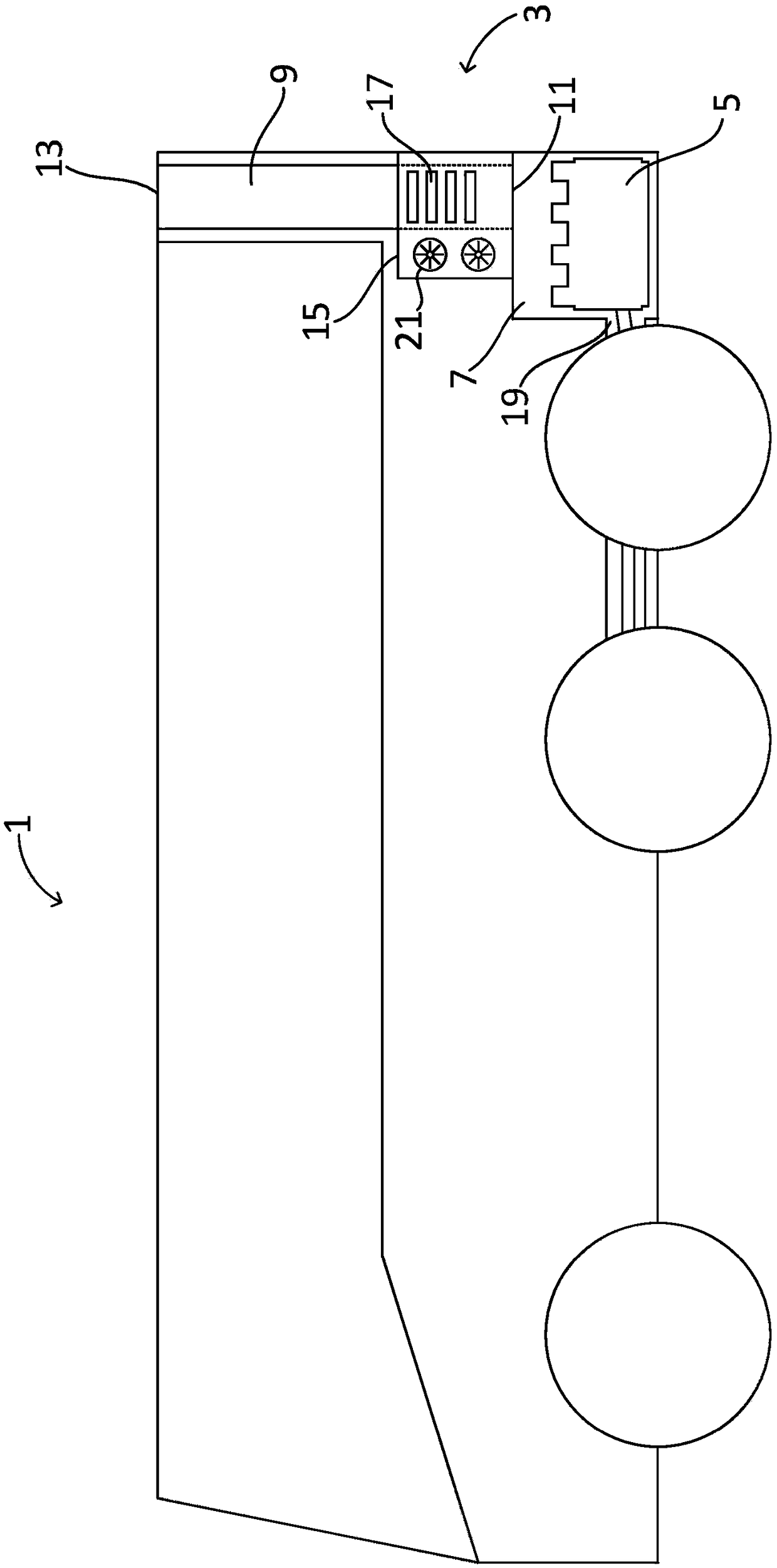
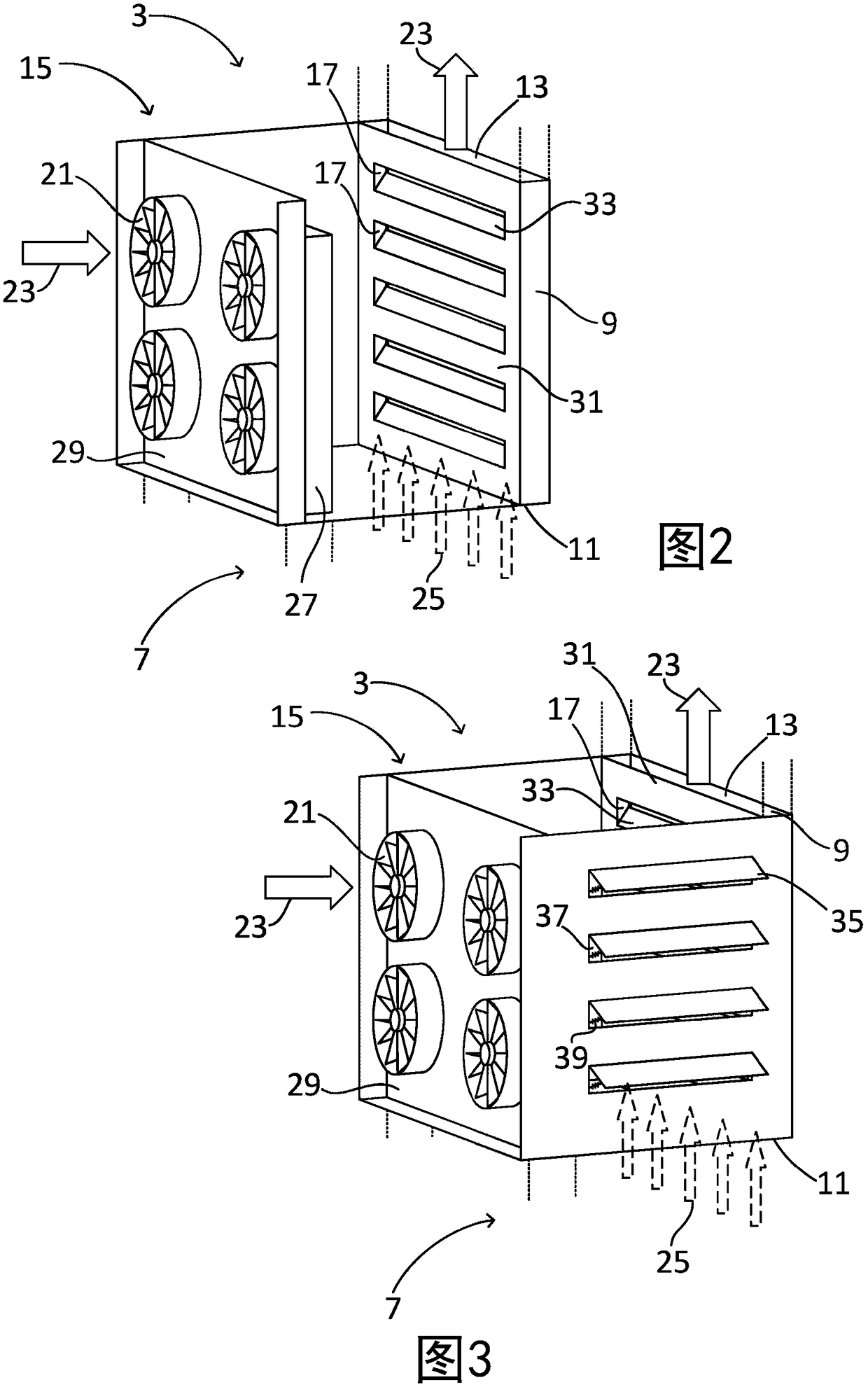
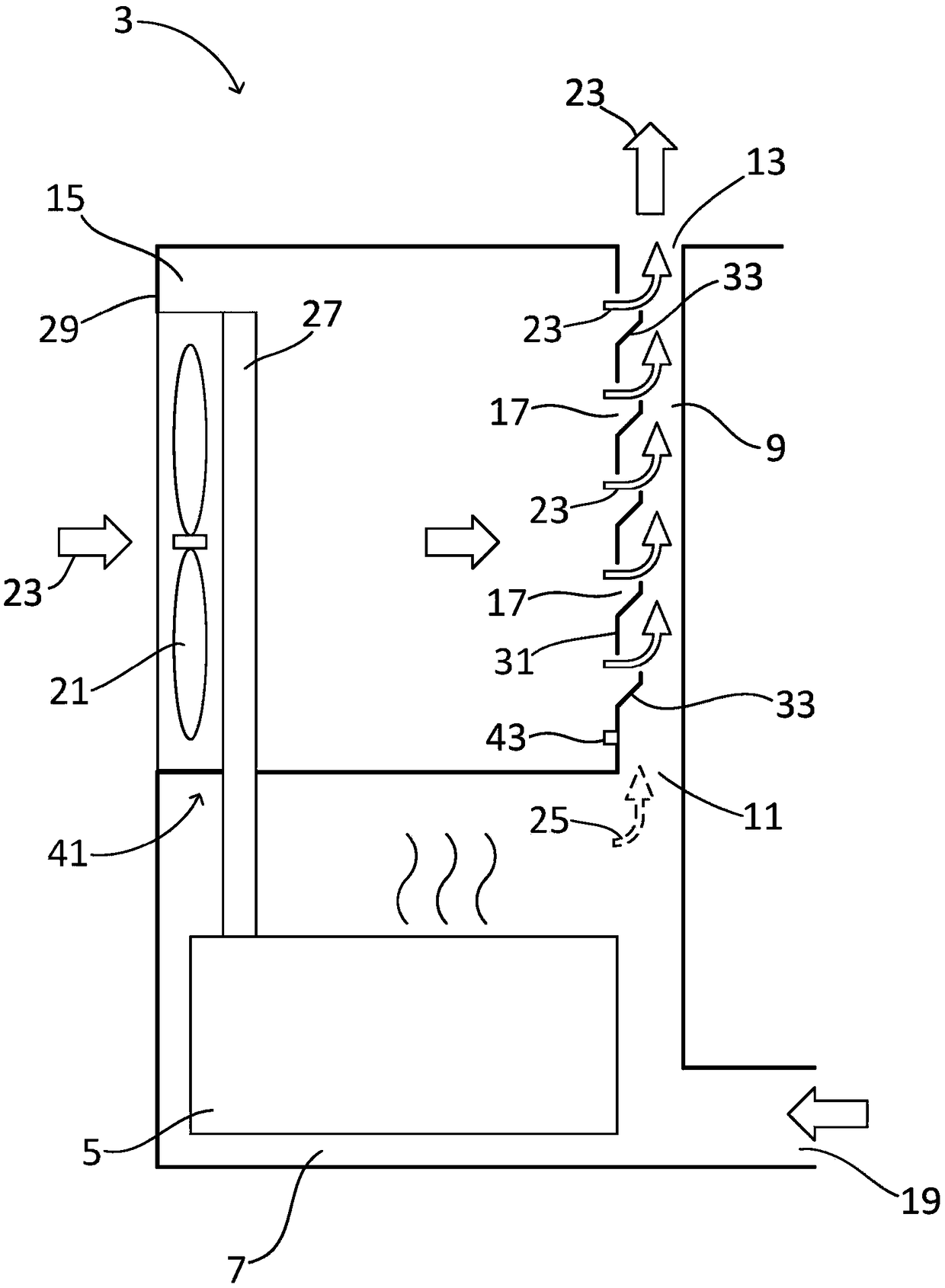
[0043] figure 1 A vehicle 1 provided with a ventilation device 3 according to the invention is schematically shown. The vehicle 1 comprises an engine 5 located in a first space 7 of the vehicle 1, a shaft 9 extending from said first space 7, said shaft 9 comprising an inlet 11 and an outlet 13, wherein the inlet 11 is arranged in contact with the first space 7 is in fluid communication, and the outlet 13 is in fluid communication with the ambient atmosphere outside the vehicle 1 . The hoistway 9 is a separate space separated from the surroundings by walls. The ventilation device 3 also comprises a second auxiliary space 15 which is arranged in the vicinity of the hoistway 9 . The hoistway 9 extends in length along the auxiliary second space 15 . The auxiliary space 15 is in fluid communication with the shaft 9 by means of a plurality of openings 17, wherein the flow of air from the auxiliary second space 15 via the shaft 9 to the surrounding atmosphere causes an ejector eff...


PUM


Abstract

The invention relates to a ventilation device for a first space (7), in particular an engine room of a vehicle (1), comprising a chimney (9) extending from said first space (7), the chimney (9) comprising an inlet (11) and an outlet (13), wherein the inlet (11) is arranged in fluid communication with the first space (7) and the outlet (13) is in fluid communication with a surrounding atmosphere. The ventilation device (3) further comprises an auxiliary second space (15), the second space (15) being arranged adjacent the chimney (9) and being in fluid communication with the chimney (9) by meansof at least one opening (17), wherein an airflow flowing from the auxiliary second space (15) to the surrounding atmosphere via the chimney (9) causes an ejector effect in the chimney (9) which ventsair from the first space (7). The invention also relates to a vehicle (1) comprising a ventilation device (3) and a method for venting a first space (7) by using a ventilation device (3).

Description

technical field [0001] The invention relates to a ventilation device, a vehicle having such a device, and a method for ventilating a heat-generating space, in particular an engine compartment of a vehicle. Background technique [0002] The invention relates to a ventilation device according to the appended claims, a vehicle having such a device, and a method for ventilating a space where heat is generated. [0003] Since many different types of machines and / or devices generate heat as a by-product of the work they perform, removing that heat is a common problem in several fields, such as industrial processes, other machines, or vehicles. Removing heat can be done in various ways, such as using fans, heat sinks, water cooling or other means. For vehicles in particular, the build-up of heat needs to be avoided since the engine, battery and other equipment can be damaged if over-exposed to heat. For example, a well cooled engine, and especially an internal combustion engine, ...

Claims


Application Information

Patent Timeline
IPC IPC(8): B60K11/06F01P1/06
CPCB60K11/06F01P1/06B60K11/04B60Y2200/143F01P2001/005
Inventor B·斯特瓦诺维奇P·乔林德
Owner SCANIA CV AB
Why Eureka
Try Eureka