Arcing fault recognition unit

A technology of fault arc and identification unit, which is applied in the direction of electrical components, measuring electricity, and only measuring current, etc., to achieve the effect of identification or extinguishment improvement

Active Publication Date: 2019-03-15
SIEMENS AG
View PDF8 Cites 2 Cited by
  • Summary
  • Abstract
  • Description
  • Claims
  • Application Information

AI Technical Summary

Problems solved by technology

[0008] This has the disadvantage that optical waveguides or optical detection systems mu

Method used


Image

  • Arcing fault recognition unit
  • Arcing fault recognition unit
  • Arcing fault recognition unit

Examples


Embodiment Construction

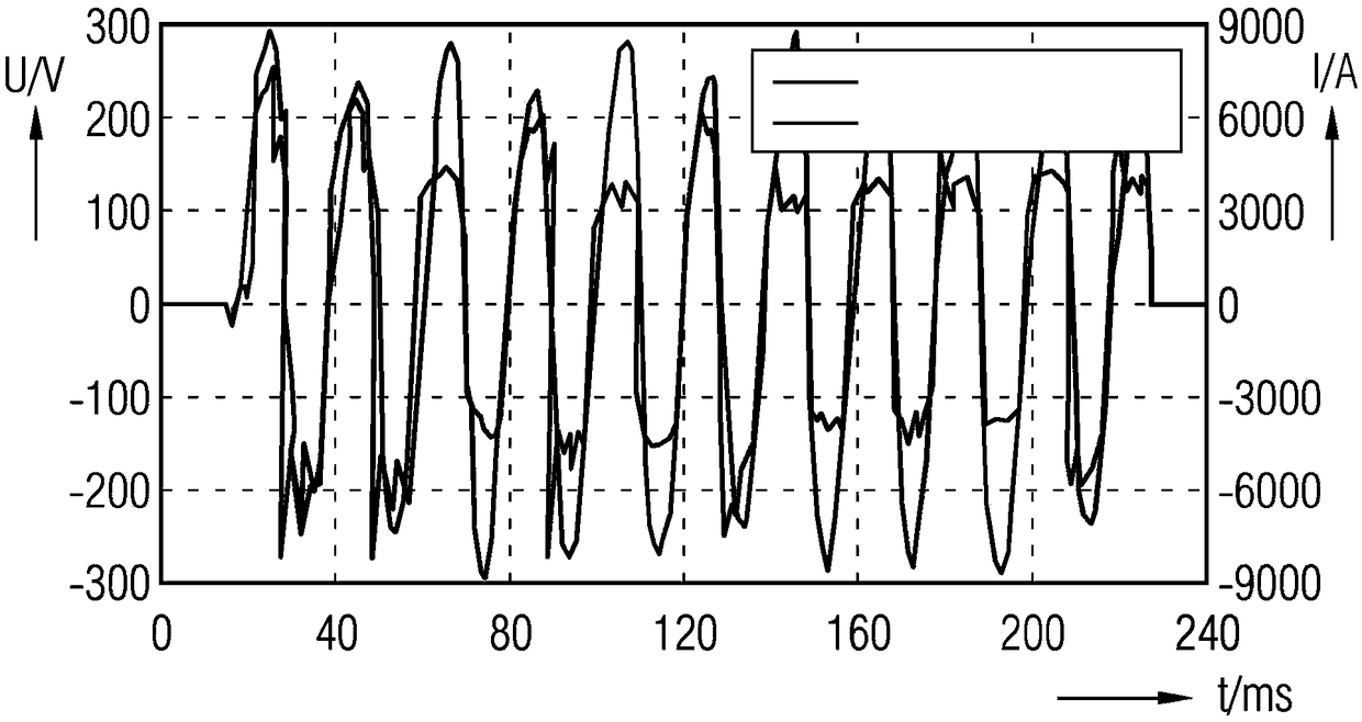
[0032] In circuits or grids where fault arcs burn, current and voltage curves with unique curves can be measured. exist figure 1 A general voltage and current curve for an arc fault is shown in . figure 1 An illustration of a graph is shown in which the time profile of the voltage (U) and current (I) after ignition of an arc or fault arc, in particular a parallel fault arc, in an electrical circuit, in particular a low-voltage circuit, is shown.

[0033]Time (t) is shown in milliseconds (ms) on the horizontal X-axis. On the vertical Y axis, the magnitude of voltage (U) is depicted in volts (V) on the left scale. The magnitude of the current (I) is depicted in amperes (A) on the right scale.

[0034] After ignition of the arc, the curve of the current (I) is approximately sinusoidal. The curve of the voltage (U) is here "sawtooth" with rapid voltage changes. Roughly explained, the first approximation of the voltage curve is rectangular rather than the usual sinusoidal curv...


PUM


Abstract

The invention relates to an arcing fault recognition unit for an electric low-voltage circuit, comprising at least one current sensor for periodically ascertaining electric current values in the electric circuit, the current sensor being connected to an analysis unit which is designed in such a way that an arcing fault recognition signal is output when a variation in the rate of current rise exceeds a first threshold value (SW1) or drops below a second threshold value (SW2).

Description

technical field [0001] The invention relates to an arc fault detection unit, a circuit breaker, a short circuit and a method for detecting an arc fault. Background technique [0002] In low-voltage circuits or installations or low-voltage networks, ie circuits with voltages up to 1000 V AC or 1500 V DC, short circuits are often associated with fault arcs occurring, for example parallel or series fault arcs. Especially in the case of high-power distribution and switching devices, this can lead to catastrophic damage to operating components, installation parts or the entire switching device if the switching off is not fast enough. In order to avoid long-lasting and large-area interruptions of the energy supply and to reduce personal injury, these arc faults, in particular high-current fault arcs or parallel fault arcs, need to be detected and extinguished within milliseconds. Traditional energy supply equipment protection systems such as fuses and circuit breakers cannot prov...

Claims


Application Information

Patent Timeline
IPC IPC(8): H02H1/00G01R31/02H02H3/44H02H3/50
CPCG01R31/1272H02H1/0015H02H3/44H02H3/50G01R19/0092H02H9/02
Inventor K.温兹拉夫J.迈耶P.谢格纳
Owner SIEMENS AG
Why Eureka
Try Eureka