
Anti-blocking scriber for test field and using method of anti-blocking scriber

A test field and scriber technology, applied in planting methods, applications, agriculture, etc., can solve the problems of time-consuming and labor-intensive, increase the labor intensity of staff, etc., and achieve the effect of convenient and quick operation, facilitate dredging, and ensure normal cutting.

Active Publication Date: 2019-03-19
济宁市农业科学研究院
View PDF7 Cites 4 Cited by
  • Summary
  • Abstract
  • Description
  • Claims
  • Application Information

AI Technical Summary

Problems solved by technology

[0004] Although the above-mentioned device can draw multiple parallel lines, the device requires the staff to manually push the scriber forward, which increases the labor intensity of the staff, and when the powder spreading funnel is blocked, it is necessary to stop the trolley for cleaning. Manual cleaning is time-consuming and labor-intensive

Method used


Image

  • Anti-blocking scriber for test field and using method of anti-blocking scriber
  • Anti-blocking scriber for test field and using method of anti-blocking scriber
  • Anti-blocking scriber for test field and using method of anti-blocking scriber

Examples


Embodiment 1

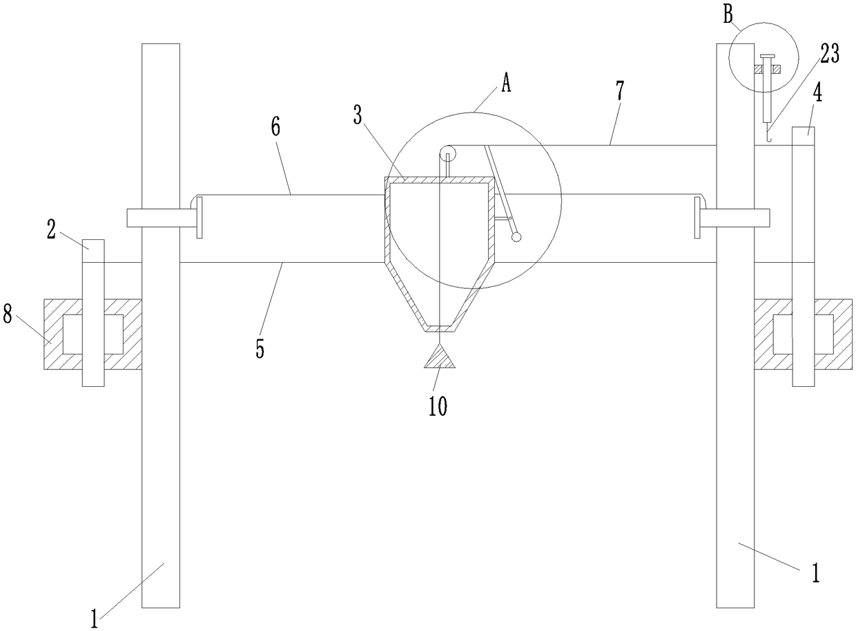
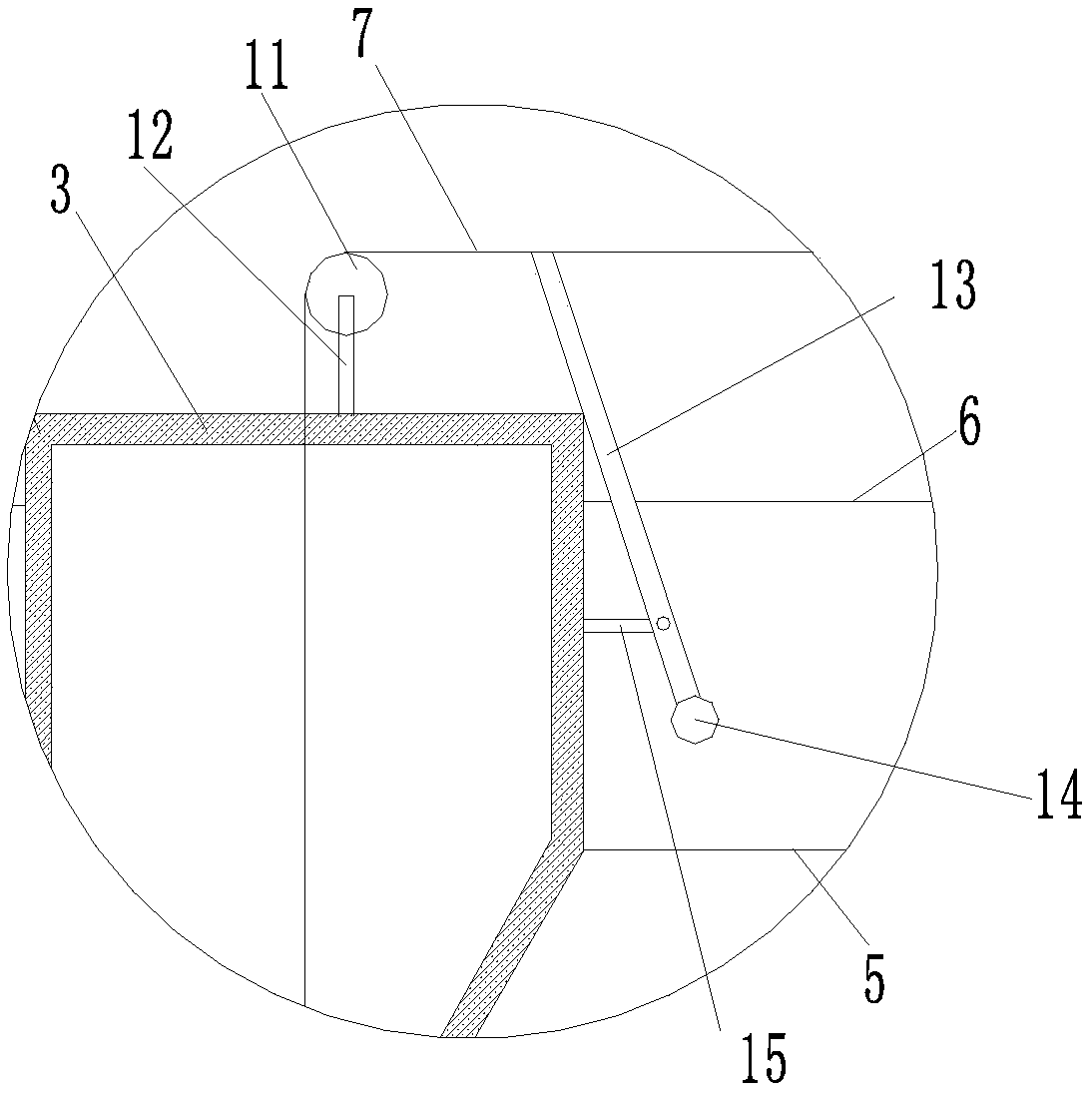
[0045] like Figure 1-7 As shown, a kind of anti-blocking marking device for a test field proposed in this embodiment includes an ash hopper 3 and a vertical pole 1, wherein the number of vertical poles 1 is provided with two, and a first pole is provided on the two vertical poles 1. The through hole 18 and the second through hole 19 are advantageous. In order to facilitate ash leakage, the bottom of the ash hopper 1 can be set as a cone, and the bottom end of the ash hopper 1 is provided with an ash outlet 32, and the outer wall of the ash hopper 1 is also provided with an ash outlet. Rope-through ring 31 is arranged, wherein the quantity of rope-through ring 31 can be set as two and is arranged symmetrically, and support plate 33 is also provided at the top of ash bucket 1; Ash bucket 3 is connected with vertical rod 1 by reciprocating mechanism, further Yes, the reciprocating mechanism may include a bracket 8, and further, there are two brackets 8, the brackets 8 are respec...

Embodiment 2

[0059] like Figure 8 As shown, other structures are the same as those in Embodiment 1, the difference is that the lifting mechanism of the ejector proposed in this embodiment can be a magnet 24, and the ejector is lifted and fixed by using the magnetic force of the magnet 24, which is very convenient and practical.

[0060] The specific usage method is as follows:

[0061] When in use, first fix the pole 1 at both ends of the test field;

[0062] The second wire rope 6 is passed through the rope ring 31, and the two ends of the second wire rope 6 are stretched into the fastening holes 91 of the first bolt 9 respectively, and the first bolt 9 is screwed into the first threaded hole 17. A bolt 9 is continuously screwed in, and the second wire rope 6 is fastened on the vertical pole 1;

[0063] A staff member rotates the first rotating shaft 2, along with the rotation of the first rotating shaft 2, drives the first steel wire rope 5 to move towards the direction close to the f...


PUM


Abstract

The invention discloses an anti-blocking scriber for a test field. The anti-blocking scriber comprises an ash bucket and upright rods, wherein totally two upright rods are arranged; an ash outlet is formed in the bottom end of the ash bucket; the ash bucket is connected with the upright rods by virtue of a reciprocating mechanism; an anti-blocking mechanism is arranged on the ash bucket and comprises a digging rope; one end of the digging rope is connected with the reciprocating mechanism; the other end of the digging rope penetrates through the inner cavity of the ash bucket so as to extend to the ash outlet and is connected with an ejector; the ejector is matched with the ash outlet; the ejector comprises a tip; a striking rod is connected onto the digging rope; a first connecting rod ishinged onto the striking rod; and the first connecting rod is connected with the outer wall of the ash bucket. By virtue of dual actions of ejecting and shaking, blanking normality is ensured, the operation is convenient and rapid, and time and labor can be saved. Meanwhile, the operation of opening and closing the ash outlet at an optional position is realized in the scribing process, the scriber is multifunctional, and the working efficiency is improved.

Description

technical field [0001] The invention relates to the technical field of scribing devices, in particular to an anti-blocking scribing device for a test field and a use method thereof. Background technique [0002] In agricultural science experiments, in order to ensure the accuracy of the experimental data and make the sowing row and plant spacing as consistent as possible, it is necessary to mark the sowing position in the experimental field before sowing. At present, the method of marking is at first to mark the row marks in the longitudinal direction according to the needs of the sowing row spacing. Since the distance in the longitudinal direction is longer, a mechanically driven row marker can be used to operate. When rowing horizontally, the following methods are mainly used: First, the method of pulling the horizontal line is adopted. Two operators stretch the thin rope, and one person in the middle steps on it or presses it with a wheelbarrow along the thin rope. Bendi...

Claims


Application Information

Patent Timeline
Patent Type & Authority Applications(China)
IPC IPC(8): A01C14/00
CPCA01C14/00
Inventor 吴静
Owner 济宁市农业科学研究院
Learn More