Supercharge Your Innovation With Domain-Expert AI Agents!

Health real-time monitoring device with sound cavity microphone array and monitoring method thereof

A microphone array and monitoring device technology, applied in stethoscopes and other directions, can solve the problems of collecting sound signals, weak positions of sound signals, uncertainties, etc., and achieve the effects of eliminating noise signal interference, accurately locating sound source positions, and improving accuracy

Inactive Publication Date: 2019-03-19
北京源动数字健康科技有限公司
View PDF4 Cites 0 Cited by
  • Summary
  • Abstract
  • Description
  • Claims
  • Application Information

AI Technical Summary

Problems solved by technology

[0004] At present, the existing monitoring devices based on the detection of sound phenomena include fetal heart rate monitoring, cardiopulmonary sound monitoring, etc. During the monitoring process, the equipment is always in close contact with the human body, and external noise, human activities, or friction with clothing will generate a lot of noise, while the human body’s All kinds of sound signals are relatively weak and their positions are uncertain. The existing sensor structure is to directly use the sensor to collect sound signals, which cannot effectively eliminate these noises, resulting in inaccurate monitoring results and increasing the difficulty of real-time monitoring.
[0005] The existing medical stethoscope has a sound chamber structure, but when using this structure, a doctor with professional knowledge needs to manually find the sound source position, and the sound signal cannot be automatically collected according to the sound source position, and the stethoscope cannot monitor the human body in real time

Method used


Image

  • Health real-time monitoring device with sound cavity microphone array and monitoring method thereof
  • Health real-time monitoring device with sound cavity microphone array and monitoring method thereof
  • Health real-time monitoring device with sound cavity microphone array and monitoring method thereof

Examples


Embodiment Construction

[0055] The embodiments of this patent will be described in detail below in conjunction with the accompanying drawings.

[0056] It should be clear that the described embodiments are only some of the embodiments of the present invention, not all of them. Based on the embodiments of the present invention, all other embodiments obtained by persons of ordinary skill in the art without making creative efforts belong to the protection scope of the present invention.

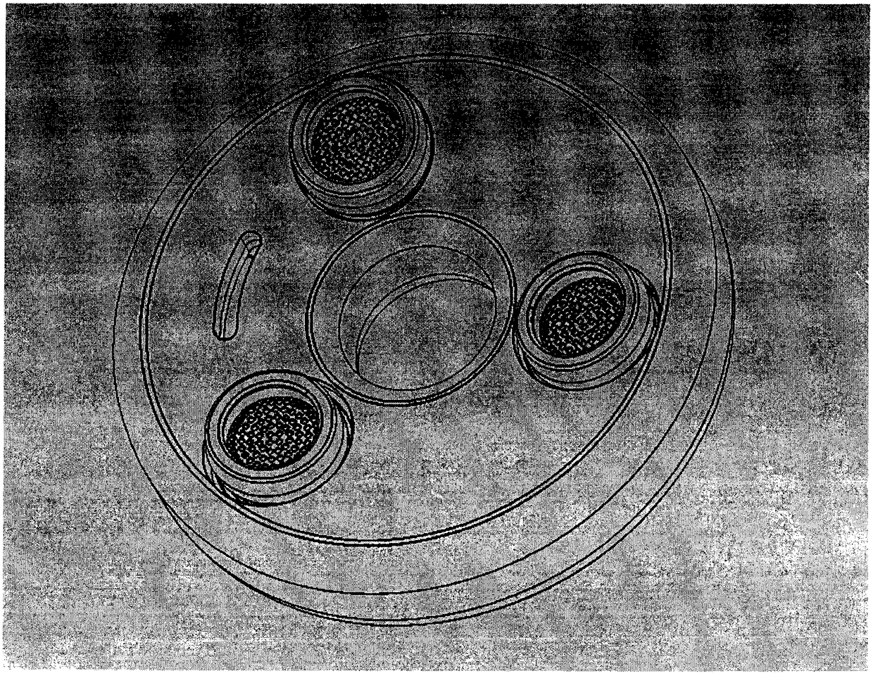
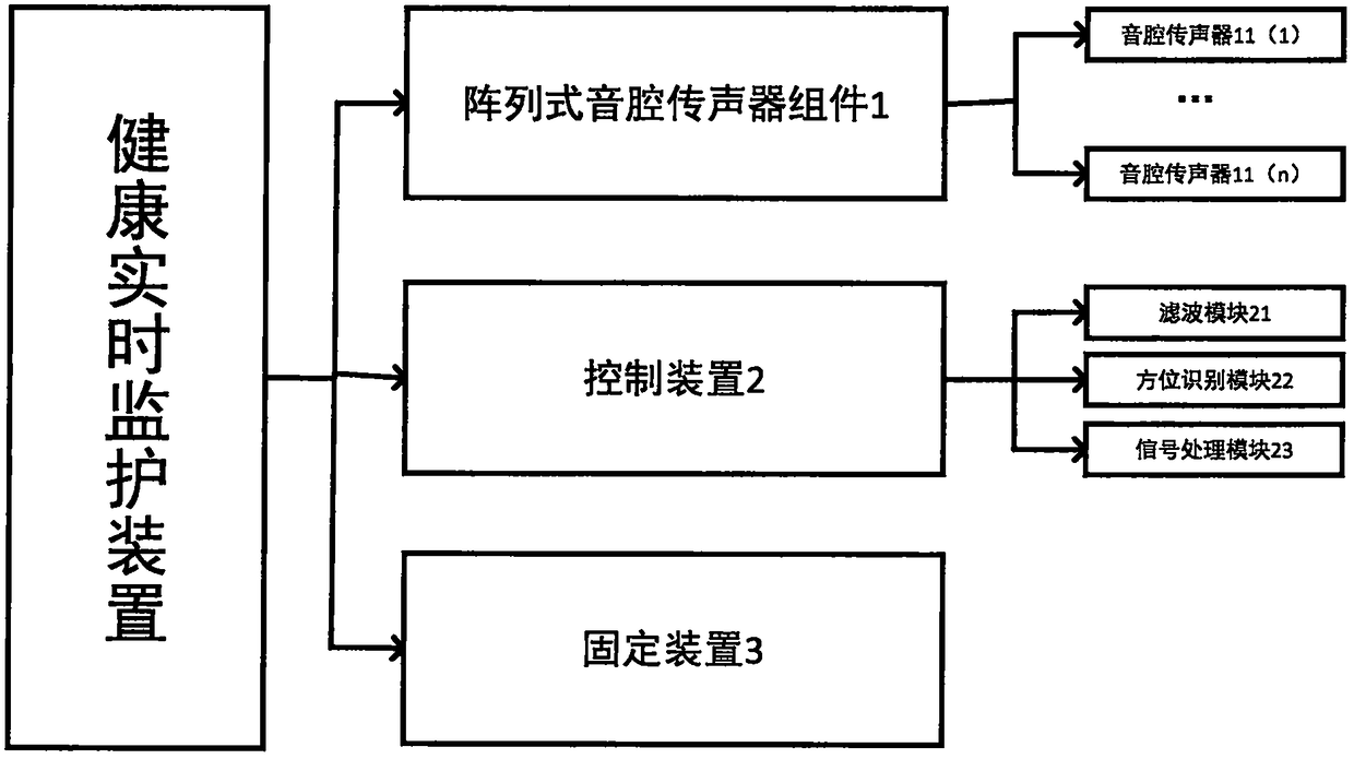
[0057] figure 1 For the health real-time monitoring device with sound cavity microphone array of the present invention, figure 2 It is a schematic structural diagram of a health real-time monitoring device with an array of sound chambers of the present invention. refer to figure 1 and figure 2 , the real-time health monitoring device includes: an array sound chamber microphone assembly 1 , a control device 2 and a fixing device 3 .

[0058] Wherein, the array type sound chamber microphone assembly 1 includes at ...


PUM


Abstract

The invention relates to a health real-time monitoring device with a sound cavity array and a monitoring method thereof. The health real-time monitoring device comprises an array type sound cavity microphone assembly, a control device and a fixing device, wherein the array type sound cavity microphone assembly comprises at least two sound cavity microphones, which are used for collecting sound emitted in a person to be tested; the control device is used for calculating the sound source position according to the signals collected by the array type sound cavity microphone assembly and carrying out post-processing on the signals collected by the array type sound cavity microphone assembly based on the sound source position to obtain real-time monitoring acoustic signals. A sound-receiving cavity is arranged in each sound cavity microphone of the array type sound cavity microphone assembly, the sound-receiving cavity is provided with an open and sealed opening, so that the tightness of thesound cavity is ensured, and the formed sound cavity microphone is used for enhancing the amplitude of received sound. Each microphone of the microphone assembly is provided with a sound cavity structure, so that the interference of noise signals can be effectively eliminated, and the accuracy of monitoring signals is improved.

Description

technical field [0001] The invention relates to a health real-time monitoring device and method with a sound cavity microphone array, belonging to the field of intelligent wearable equipment and medical equipment. Background technique [0002] At present, personal real-time health care monitoring has gradually played an important role in people's lives. [0003] Personal real-time health care monitoring is a new type of medical care model. Its appearance enables the existing hospital functions to be extended to the family. It not only provides a convenient and comfortable living environment, but also undertakes health education, chronic disease detection, fetal health monitoring, Responsibilities such as elderly life care and health care have very broad market potential. [0004] At present, the existing monitoring devices based on the detection of sound phenomena include fetal heart rate monitoring, cardiopulmonary sound monitoring, etc. During the monitoring process, the ...

Claims


Application Information

Patent Timeline
IPC IPC(8): A61B7/04
CPCA61B7/04
Inventor 吴文焘张彧田斌
Owner 北京源动数字健康科技有限公司
Features
  • R&D
  • Intellectual Property
  • Life Sciences
  • Materials
  • Tech Scout
  • Unparalleled Data Quality
  • Higher Quality Content
  • 60% Fewer Hallucinations
Learn More