Turning tool capable of achieving rapid clamping and rapid clamping method using same

A clamping and fast technology, used in clamping, positioning devices, manufacturing tools, etc., can solve the problems of insufficient strength of thin-walled parts, deformation and displacement of parts, affecting the quality of parts, etc., to break through the bottleneck of mass production and achieve mass production. Processing, the effect of improving production efficiency

Pending Publication Date: 2019-03-19
SICHUAN FUTURE AEROSPACE IND LLC
View PDF13 Cites 5 Cited by
  • Summary
  • Abstract
  • Description
  • Claims
  • Application Information

AI Technical Summary

Problems solved by technology

[0004] The purpose of the invention is to solve the technical problems in the prior art that when the thin-walled parts with undercuts at the upper and lower ends are turned, the parts are deformed and displaced due to unstable clamping, resulting in unqualified parts, and to provide A quick clamping turning tool, the turning tool forms a circular support for the part from the inner wall of the part through the upper and lower positioning of the turning tool, which solves the problem that the insufficient strength of the thin-walled part affects the quality of the part during processing, and realizes Quick clamping and tight fit inside are conducive to improving cutting parameters, improving production efficiency, realizing batch processing, and breaking through the bottleneck of mass production

Method used


Image

  • Turning tool capable of achieving rapid clamping and rapid clamping method using same
  • Turning tool capable of achieving rapid clamping and rapid clamping method using same
  • Turning tool capable of achieving rapid clamping and rapid clamping method using same

Examples


Embodiment 1

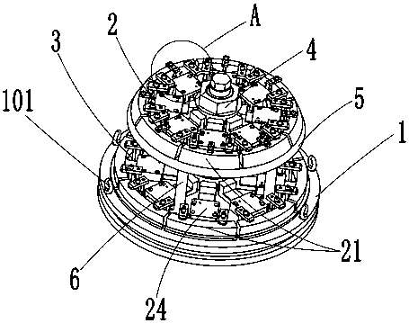
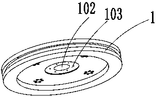
[0048]The quick clamping turning tool of the present invention comprises a base 1 with a circular structure, and a lower positioning device 3 and an upper positioning device 2 installed on the base 1 sequentially from bottom to top, and also includes a driving device 4, and the upper positioning device 2 and the lower positioning device The positioning device 3 is composed of several support blocks 21, and the support blocks 21 are arranged alternately to form a circular support for the part 7. The outer wall of each support block 21 is provided with a fitting surface 2112 matching the inner wall of the part 7, so The driving device 4 can drive the supporting block 21 in the upper positioning device 2 to move synchronously, and can drive the supporting block 21 in the lower positioning device 3 to move synchronously.

[0049] Specifically, several of the supporting blocks 21 include several first supporting blocks 211 and several second supporting blocks 212, several of the fir...

Embodiment 2

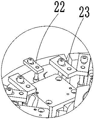
[0060] In this embodiment, the difference from Embodiment 1 is that the second pressing device 23 for pressing the support block 21 is respectively provided on the mounting plate 5 and the base 1, and the eight first pressing devices 23 are used to compress the supporting blocks 21. A support block 211 is pressed onto the mounting plate 5, and eight second support blocks 212 are pressed onto the base 1, which is conducive to processing the fitting surface 2112 of the support block 21 during the processing stage of the tooling, so that when the tooling is used The bonding surface 2112 of the support block 21 is better bonded to the inner wall of the component 7 .

Embodiment 3

[0062] The present invention also provides a method for fast clamping, using the fast clamping turning tool as described in any one of embodiment 1 or 2, the steps are as follows:

[0063] A. Install the base 1 on the processing table;

[0064] B. Adjust the compression nut 403 and the second screw rod 4041 so that the first expansion core 402 and the second expansion core 404 are in a free state;

[0065] C. Install part 7 from above the tooling;

[0066] D. Adjust the second screw 4041 so that the second expansion core 404 goes down, so that the second support block 212 tightens the inner wall of the lower section 702 of the part 7;

[0067] E. Adjust the compression nut 403 so that the first expansion core 402 goes down, so that the first support block 211 tightens the inner wall of the upper section 701 of the part 7;

[0068] F. Turn the pressing plate on the first pressing device 22 so that the height of the pressing plate matches the part 7, and then turn the pressing...


PUM


Abstract

The invention relates to the technical field of machining of thin-walled parts, in particular to a turning tool capable of achieving rapid clamping. The turning tool comprises a base, a lower positioning device and an upper positioning device, wherein the lower positioning device and the upper positioning device are sequentially installed on the base from bottom to top, the turning tool further comprises a driving device, each of the upper positioning device and the lower positioning device is composed of a plurality of supporting blocks, moreover, the plurality of supporting blocks of each ofthe upper positioning device and the lower positioning device are arranged at intervals to form a circular support for the part correspondingly, a fitting surface matched with the inner wall of the part is arranged on the outer wall of each supporting block, the driving device can drive the supporting blocks in the upper positioning device to move synchronously, and can drive the supporting blocks in the lower positioning device to move synchronously. The turning tool achieves positioning through an upper section and a lower section, the circular supports are formed to the part from the innerwall of the part, then the problem that the quality of the part is influenced in the machining process due to insufficient strength of the thin-wall part is solved, the thin-walled part can be quickly clamped, the inner parts are tightly attached, then the cutting parameters can be improved, the production efficiency can be improved, batch machining can be realized, and the mass production chokepoint can be broken through.

Description

technical field [0001] The invention relates to the technical field of machining of thin-walled parts, in particular to a fast clamping turning tool and a fast clamping method thereof. Background technique [0002] In the turning processing of thin-walled parts such as engines, spacecraft shells, and missile barrels, conventional processing methods generally require multiple clamping and repeated positioning, and there are problems such as displacement and deformation during processing. Unstable clamping is prone to the problem of knife chatter. [0003] like Figure 9 As shown, it is an aircraft engine combustion chamber casing part 7. It is necessary to process the upper section 701 and the lower section 702 of the part 7, and trim the upper and lower sections of the part to facilitate the later welding process. However, the upper and lower sections of the part both extend to the inside of the part. , showing two undercut shapes, the undercut angle is relatively large, an...

Claims


Application Information

Patent Timeline
Patent Type & Authority Applications(China)
IPC IPC(8): B23Q3/06
CPCB23Q3/065
Inventor 刘海波马洪杰罗敏锐
Owner SICHUAN FUTURE AEROSPACE IND LLC
Why Eureka
Try Eureka