Eureka AIR delivers breakthrough ideas for toughest innovation challenges, trusted by R&D personnel around the world.

Novel magnetron sputtering device

A magnetron sputtering device and a new type of technology, which are applied in sputtering coating, ion implantation coating, metal material coating process, etc., can solve the problems of waste, target atom shedding, uneven magnetic field distribution, etc. efficiency, avoid waste, and improve the effect of film thickness uniformity

Pending Publication Date: 2019-03-19
LAKESIDE PHOTOELECTRONICS TECH JIANGSU CO
View PDF0 Cites 0 Cited by
  • Summary
  • Abstract
  • Description
  • Claims
  • Application Information

AI Technical Summary

Problems solved by technology

[0002] In the existing conventional sputtering device, due to the uneven distribution of the magnetic field, the middle part of the target is consumed faster than the two sides, resulting in waste
At the same time, a small amount of ions bombard the substrate during the sputtering process, causing the target atoms that have been sputtered onto the substrate to fall off

Method used


Image

  • Novel magnetron sputtering device
  • Novel magnetron sputtering device
  • Novel magnetron sputtering device

Examples


Embodiment Construction

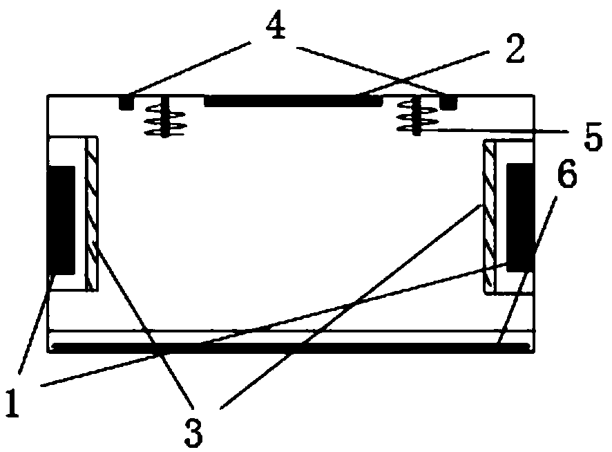
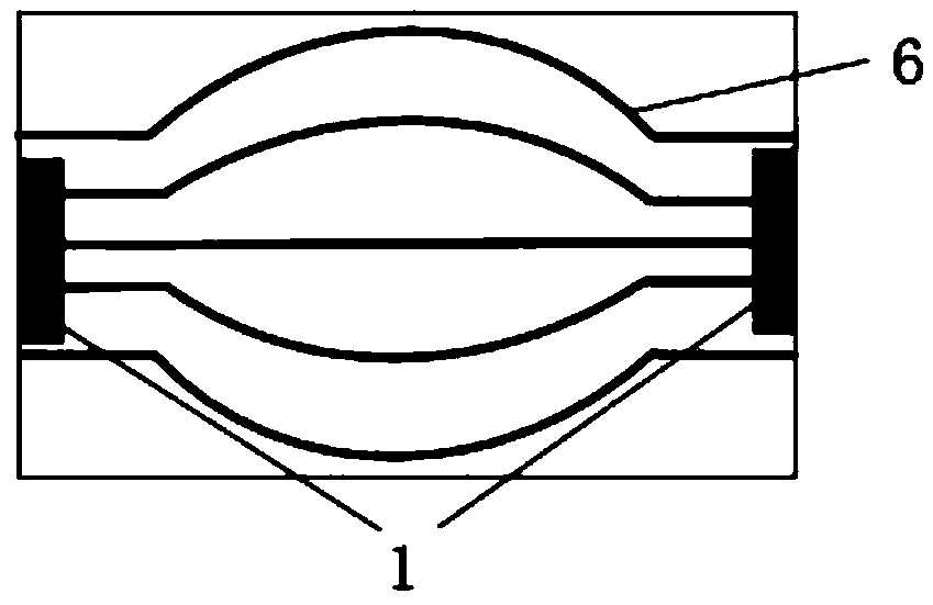
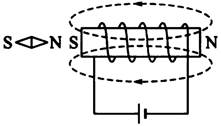
[0019] Such as Figures 1 to 3 As shown, a new type of magnetron sputtering device includes a target 1 located in the chamber and a substrate 2 that can move back and forth. A protection valve 3 is provided directly in front of the target 1, and the process position of the substrate 2 is on both sides. The first solenoids 4 are respectively provided, and the first solenoids 4 are made by winding electric wires on the outer peripheral side of the hollow tube in one direction, and the side of the first solenoids 4 facing away from the base plate 2 corresponds to The process position of the substrate 2 is provided with a laser positioner 5, and the protection valve 3 and the laser positioner 5 are both connected to the controller, and the controller is used to detect that the substrate 2 moves to the process position when the laser positioner 5 receives control the protection valve 3 to open, otherwise the protection valve 3 remains normally closed. The bottom of the chamber is ...


PUM


Abstract

The invention discloses a novel magnetron sputtering device. The novel magnetron sputtering device comprises target materials located in a chamber and a base plate that can be moved back and forth. Protection valves are arranged in front of the target materials, and first solenoids are arranged on the two sides of the process position of the base plate. Laser locators are arranged on the sides, which are back on to the base plate and correspond to the process position of the base plate, of the first solenoids. The protection valves and the laser locators are connected with a controller, and the controller is used for controlling the protection valves to open when receiving the signal detected by the laser locators that the base plate moves to the process position, otherwise the protectionvalves remain normally closed. The novel magnetron sputtering device improves the utilization rate of the target materials and promotes film thickness uniformity.

Description

technical field [0001] The invention relates to a novel magnetron sputtering device. Background technique [0002] In the existing conventional sputtering device, due to the uneven distribution of the magnetic field, the middle part of the target is consumed faster than the two sides, resulting in waste. At the same time, a small amount of ions bombard the substrate during the sputtering process, causing the target atoms that have been sputtered onto the substrate to fall off. Contents of the invention [0003] In order to solve the above technical problems, the object of the present invention is to provide a new type of magnetron sputtering device, which improves the utilization rate of the target material and improves the uniformity of film thickness. [0004] In order to solve the problems of the technologies described above, the present invention adopts the following technical solutions: [0005] A new type of magnetron sputtering device, including a target located i...

Claims


Application Information

Patent Timeline
IPC IPC(8): C23C14/35C23C14/54
CPCC23C14/351C23C14/54
Inventor 褚天舒
Owner LAKESIDE PHOTOELECTRONICS TECH JIANGSU CO
Why Eureka
Eureka Blog
Learn More