Soil extrusion expansion anchor rod structure

An expansion bolt and bolt technology, applied in basic structure engineering, sheet pile wall, excavation and other directions, can solve the problems of insufficient anchoring force, burst failure, insufficient mechanical properties, etc., to achieve strong practicability, reduce friction resistance, Guarantee the effect of anchoring force

Inactive Publication Date: 2019-03-19
WEST ANHUI UNIV
View PDF4 Cites 5 Cited by
  • Summary
  • Abstract
  • Description
  • Claims
  • Application Information

AI Technical Summary

Problems solved by technology

In the existing inflatable anchor rod, the port of the airbag is not restricted, and the airbag itself has no protection device, which is very prone to burst failure
Moreover, the smooth contact between the inflatable anchor rod and the anchor hole results in insufficient anchoring force between the two.
In view of this, the existing patent notification number is CN207130730U, which discloses a soil-squeezing expansion anchor, but there are disadvantages in the use of this anchor: the steel bars arranged on the surface of the anchor can increase the anchoring force, but the same also It will increase the resistance when conveying the anchor rod, and the whole anchor rod is composed of two half cylinders, and its overall mechanical properties are not enough

Method used


Image

  • Soil extrusion expansion anchor rod structure
  • Soil extrusion expansion anchor rod structure
  • Soil extrusion expansion anchor rod structure

Examples


Embodiment 1

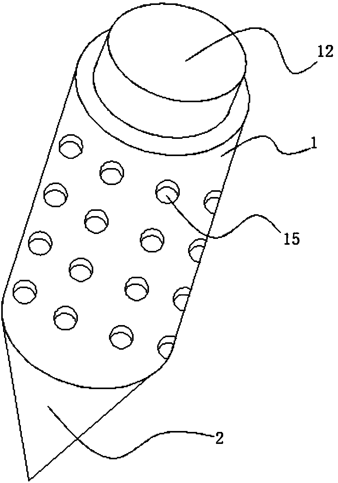
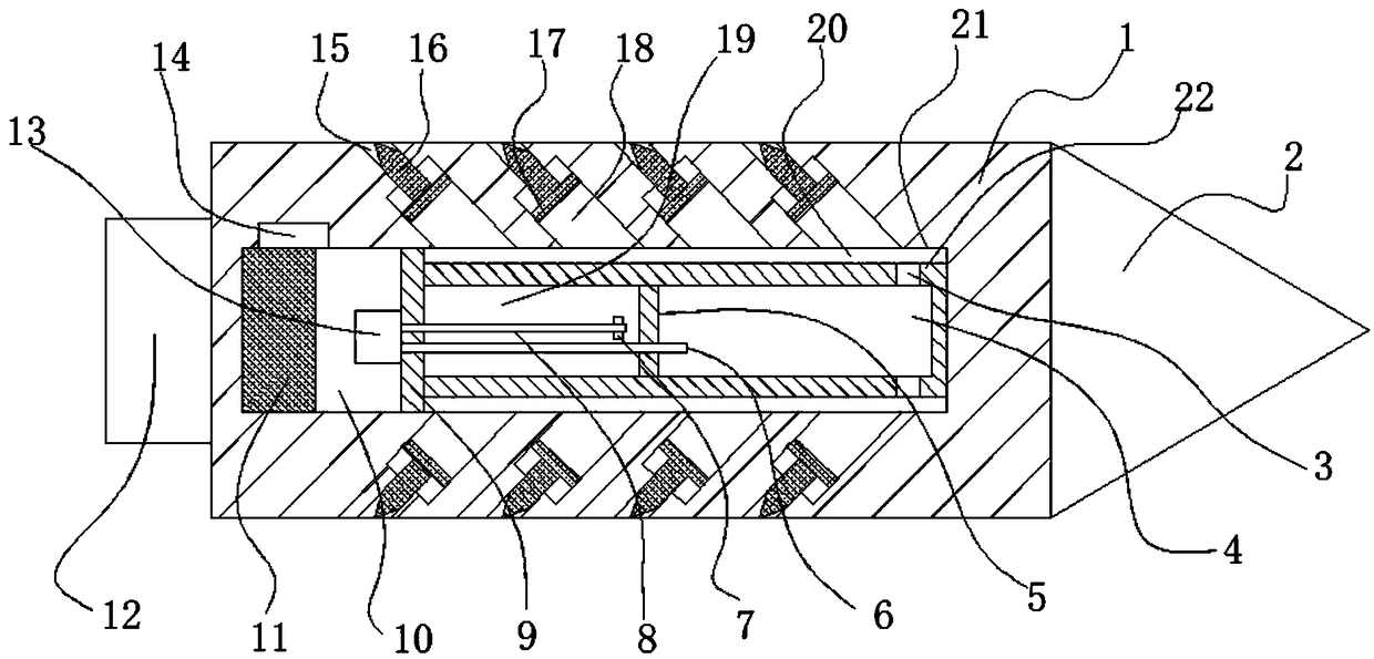
[0023] see Figure 1~3 , in an embodiment of the present invention, a soil-squeezing expansion anchor structure includes an anchor body 1, the anchor body 1 is a cylindrical structure integrally formed, the right end of the anchor body 1 is provided with a tip 2, and the anchor There is an installation cavity 21 inside the rod body 1, and the left port of the installation cavity 21 is fixed with a cover by welding. The inside of the anchor rod body 1 where the cover is located is provided with a transmission block 12, and the transmission block 12 enters the interior of the anchor hole with the conveying device. The power mechanism of the installation chamber 21 is provided with several piston chambers 18 and storage holes 15 on the wall of the installation chamber 21. The storage chamber 15 communicates with the piston chamber 18. The piston chamber 18 is inclined against the left end of the bolt body 1, and the piston The included angle between the axis of the chamber 18 and...

Embodiment 2

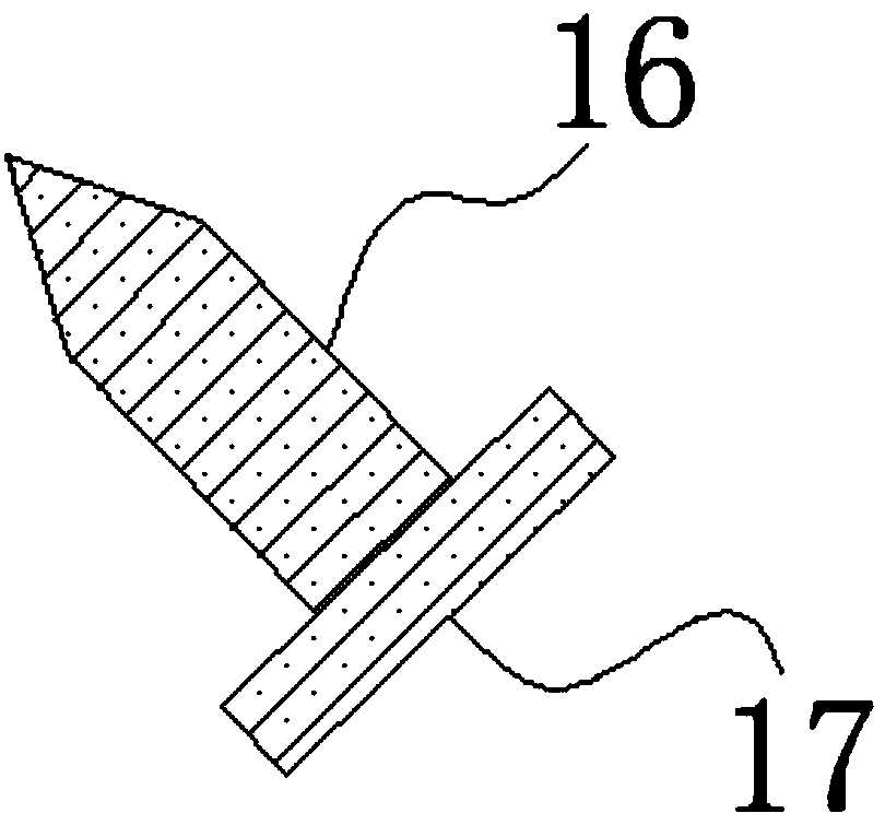
[0029] The difference from Embodiment 1 is that in order to improve the gripping effect of the anchor rod 16, the anchor rod 16 here can be arranged in the shape of a rectangular plate, and the outer end of the rectangular plate is a pointed end.


PUM


Abstract

The invention discloses a soil extrusion expansion anchor rod structure. The structure comprises an anchor rod main body; the anchor rod main body is of a cylindrical structure integrally molded; a sharp end is arranged at the right end of the anchor rod main body; a mounting cavity is formed in the anchor rod main body; a sealing cover is fixed in a left port of the mounting cavity through welding; a transmission block is arranged in the anchor rod main body of the sealing cover; the transmission block is connected with a power mechanism for conveying devices into an anchor hole during acting; multiple piston cavities and storage holes are formed in a wall of the mounting cavity; storage cavities communicate with the piston cavities; piston plates are slidingly arranged in the piston cavities; and anchoring rods are fixed at the upper ends of the piston plates. The structure is optimized aiming at the defects of a traditional device, is provided with the anchoring rods capable of realizing extension storage, can reduce the friction resistance when conveying the anchoring rods in the anchor hole, guarantees the anchoring force, and achieves high practicability.

Description

technical field [0001] The invention relates to the technical field of slope support, in particular to a soil-squeezing expansion bolt structure. Background technique [0002] Slope support refers to the support, reinforcement and protection measures taken on the slope to ensure the safety of the slope and its environment. The commonly used support structure types are: gravity retaining wall, buttress retaining wall, cantilever support, slab rib or lattice anchor retaining wall support, row pile anchor retaining wall support, anchor shotcrete Support, slope method. [0003] During the slope construction process, the pre-holed grouting anchors cannot be recycled, and will be left on the construction site to form obstacles after use, and the anchoring force can only be increased through extremely limited methods, such as increasing the anchor Diameter, length, etc. to achieve. In the existing inflatable anchor rod, the port of the airbag is not restricted, and the airbag it...

Claims


Application Information

Patent Timeline
IPC IPC(8): E02D17/20E02D5/74
CPCE02D5/74E02D17/20
Inventor 戈海玉戈壁崔明珠
Owner WEST ANHUI UNIV
Why Eureka
Try Eureka