Positioning support rod with same joint and support structure thereof

A technology for positioning support rods and supporting structures, which is applied to building construction, on-site preparation of building components, formwork/formwork/working frames, etc., can solve problems such as low construction efficiency, high cost, and complex structure, and achieve Convenience and the effect of improving construction efficiency

Active Publication Date: 2019-03-19
朱宏宇
View PDF8 Cites 2 Cited by
  • Summary
  • Abstract
  • Description
  • Claims
  • Application Information

AI Technical Summary

Problems solved by technology

[0003] The purpose of the present invention is to provide a positioning support bar with the same joint and its support structure, to solve the technical problems of traditional formwork system structure complex, low construction efficiency and high cost; and to solve the problems of improving transportation efficiency and component recycling rate

Method used


Image

  • Positioning support rod with same joint and support structure thereof
  • Positioning support rod with same joint and support structure thereof
  • Positioning support rod with same joint and support structure thereof

Examples


Embodiment Construction

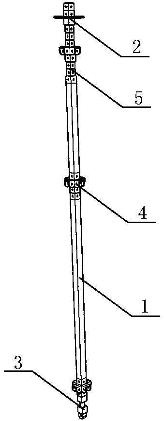
[0035] Examples see figure 1 As shown in the same-section positioning support rod, the main body of the support rod 1 is a standpipe; the upper end of the standpipe has a positioning joint 2, and the lower end has a positioning head 3, forming an upper and lower same-section positioning support rod. The standpipe includes at least one square pipe segment, and adjacent segments are connected by pin tubes; both ends of the pin tubes are correspondingly inserted into the segments and connected by pin shafts.

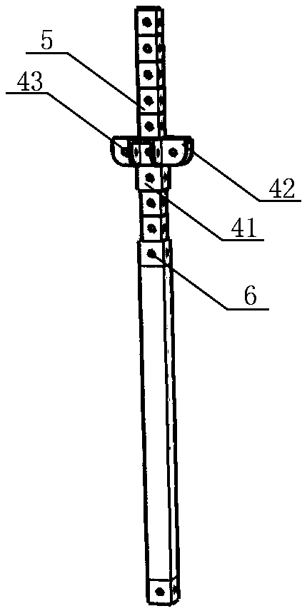
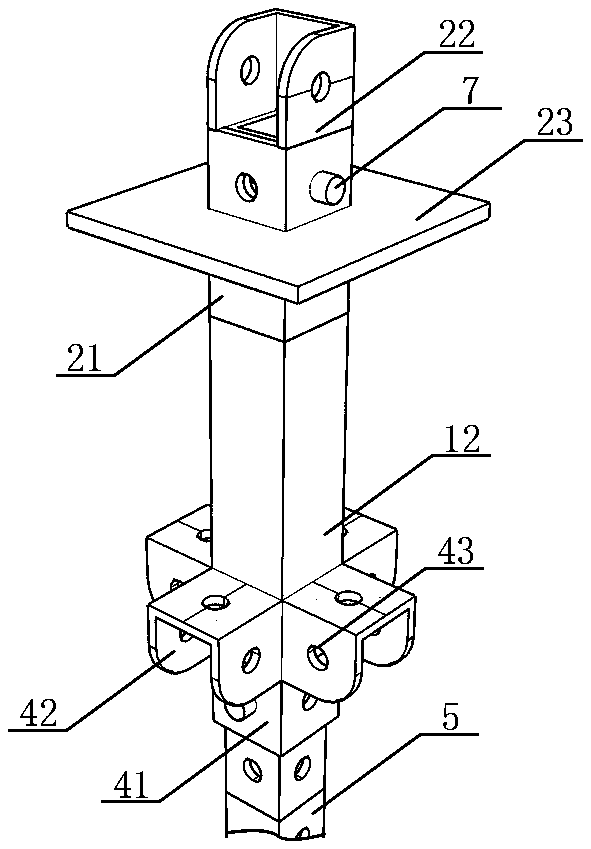
[0036] see figure 2 As shown, the standpipe is made of a square tube, and at least one pair of opposite side walls at both ends of the square tube has pin holes 6; The pin shaft 7 is fixed to form a sleeved connection; the standpipe and the pin tube form a combined pipe that is sleeved and connected to each other;

[0037] The pin tube is a square tube with an outer diameter corresponding to the inner diameter of the standpipe, with pin holes 6 on at least one pair of op...


PUM


Abstract

The invention relates to a positioning support rod with the same joint and a support structure thereof. A main body of a support rod is a vertical pipe; the upper end of the vertical pipe is providedwith a positioning joint, and the lower end of the vertical pipe is provided with a positioning head to form the positioning support rod with the same joint. The support structure comprises the support rod and a transverse pipe, wherein the support rod is arranged below the floor slab to be poured in the layer, the transverse pipes are connected between the supporting rods, and a panel is arrangedon the support rod and the transverse pipe at the uppermost end. According to the applying of the positioning support rod with the same joint, the purpose of one-time positioning of multi-layer pouring is achieved; the position of the support rod of a support frame body is only required to be positioned on the first layer; during pouring of the subsequent floor, the positioning head of the support rod is correspondingly connected with the positioning joint on the poured floor, and the positioning installation of the upper support frame body can be achieved; the convenience of construction isachieved, and the construction efficiency is improved. According to the positioning support rod with the same joint and the support structure thereof, the components are connected by a pin shaft, andthe positioning head is butted by a vertical screw rod, so that the support frame body can bear tensile force to a certain extent, and the integral transportation of the support frame body is achieved. The positioning support rod with the same joint and the support structure thereof can be widely applied to a template system.

Description

technical field [0001] The invention relates to the field of building construction, in particular to a construction formwork. Background technique [0002] At present, for concrete pouring construction, the support of the formwork system is an indispensable process. Its structure includes a panel system and a support system, but the traditional formwork system has the following defects: the formwork system cannot bear tension, but can only bear pressure. Therefore, the formwork system cannot be transported as a whole; in addition, the formwork system needs to be re-positioned for each layer of the structure to be poured, which is cumbersome and inefficient; finally, the high-precision positioning of the upper and lower formwork systems cannot be satisfied, and deviations often occur between different floors. have an impact on later construction. Contents of the invention [0003] The purpose of the present invention is to provide a joint positioning support bar and its su...

Claims


Application Information

Patent Timeline
Patent Type & Authority Applications(China)
IPC IPC(8): E04G17/00E04G11/48
CPCE04G11/48E04G17/00
Inventor 朱宏宇
Owner 朱宏宇
Why Eureka
Try Eureka