Measuring device and method for three-direction force of knife roller used in rotary tillage soil tank test bench

A measuring device and three-dimensional force technology, which is applied in the direction of measuring device, force/torque/work measuring instrument, instrument, etc. Unfavorable problems such as the analysis of the three-dimensional force of the knife roll, and achieve the effect of simple structure, high reliability, and reduced width accuracy.

Inactive Publication Date: 2020-07-31
HUAZHONG AGRI UNIV
View PDF23 Cites 0 Cited by
  • Summary
  • Abstract
  • Description
  • Claims
  • Application Information

AI Technical Summary

Problems solved by technology

However, conventional three-way force sensors can only measure three-way forces on stationary or planar moving parts. For rotational motion, since there are no relatively rotating parts inside the three-way force sensor, it cannot be directly connected to the rotating parts like a dynamic torque sensor. Take data measurements
In order to solve this problem, the usual practice is to regard the rotating parts and the frame as a whole, and then install or embed the sensor on the frame for indirect three-way force measurement, such as the invention patent CN201410425021.8 and the invention patent CN201611005215 .8, but this measurement method has the following problems: (1) It is necessary to have a high installation accuracy of the rotating parts and the frame to ensure that the force transmission is not offset by the gap, otherwise it will seriously affect the accuracy of the measurement. It is easy to cause measurement error when it is easily disturbed by other external forces
(2) Since the rotation angle data cannot be collected only by the three-way force sensor, this kind of three-way force measuring device can usually only measure the relationship between time and three-way force, but cannot measure the relationship between angle and three-way force, which is not conducive to the knife roller Comprehensive analysis of three-way force
(3) During the experiment, it is often necessary not only to measure the force of the knife roll under the fixed rotation state, but also to measure the force of the knife roll in different moving directions. At this time, power is needed to drive the frame, which leads to The force bearing system of the frame is relatively complicated. If the three-way force measuring device is installed on the frame, it will obviously not reflect the real force of the three-way force on the cutter roller.

Method used


Image

  • Measuring device and method for three-direction force of knife roller used in rotary tillage soil tank test bench
  • Measuring device and method for three-direction force of knife roller used in rotary tillage soil tank test bench
  • Measuring device and method for three-direction force of knife roller used in rotary tillage soil tank test bench

Examples


Embodiment Construction

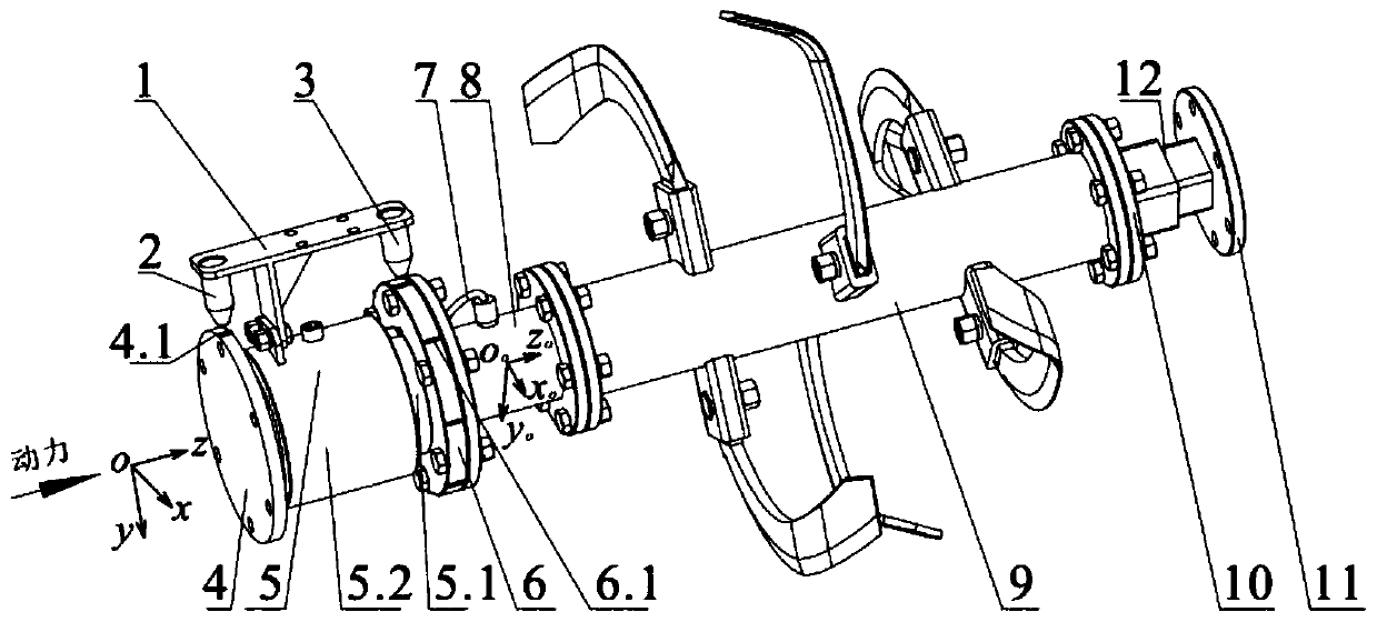
[0037] Below in conjunction with accompanying drawing, measuring device of the present invention is described further:

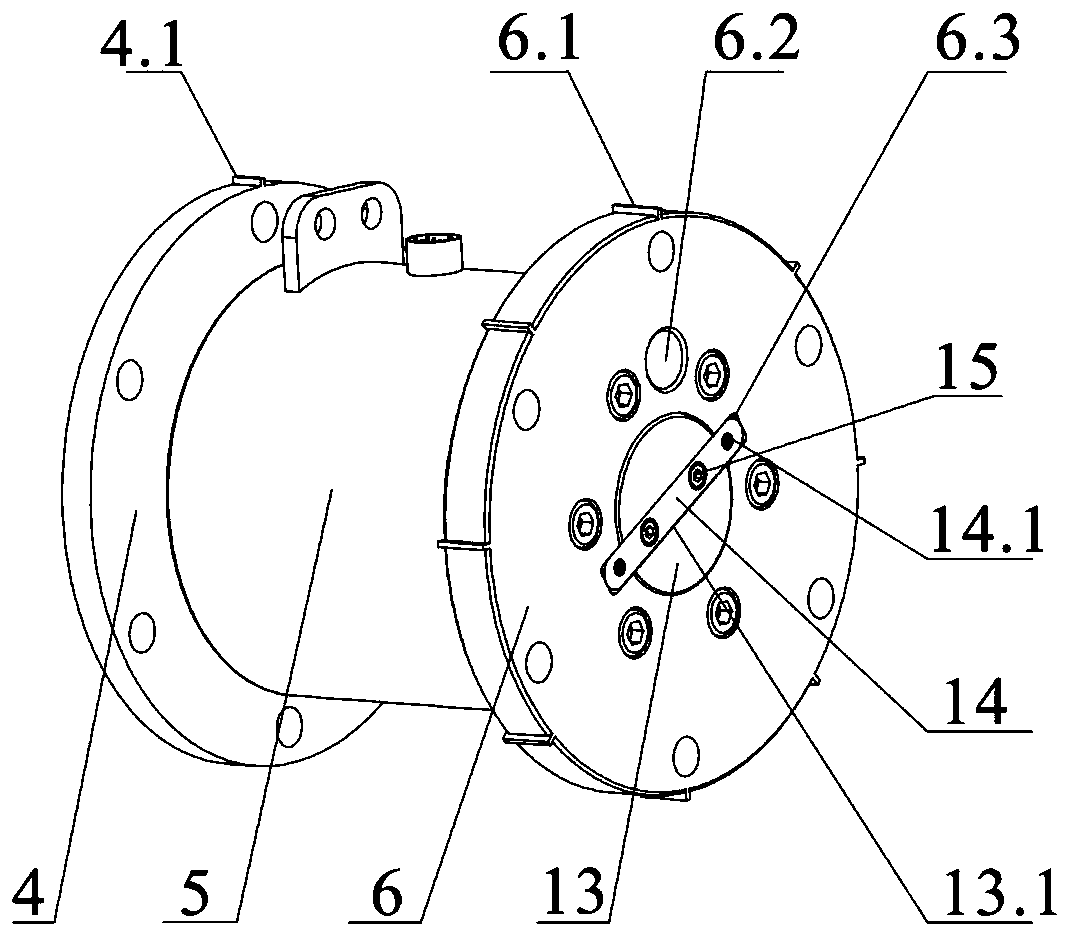
[0038] see figure 1 , the measuring device of the present invention comprises a three-way force sensor 8 whose rear end can be connected with one end of the knife roller 9, and the front end of the three-way force sensor 8 is connected with an indexing disk 6, and the indexing disk 6 is connected to the initial stage via a transmission shaft 13. The transmission shaft 13 is equipped with a conductive slip ring 5. The structural principle of the conductive slip ring 5 is the prior art, mainly including the rotor 5.1 of the inner ring and the stator 5.2 of the outer ring. The brush structure of the ring connects the rotor 5.1 with the stator 5.2, the rear end of the rotor 5.1 is connected with the index disc 6 by bolts, the width of the rotor 5.1 is larger than that of the stator 5.2, and the gap between the rotor 5.1 and the transmission shaft 13 Cooperate; ...


PUM


Abstract

The invention discloses a cutter shaft triaxial force measuring device for a rotary tillage soil groove experiment platform and a measuring method. An index disc is connected with the front end of a triaxial force sensor, the index disc is connected with an initial position disc through a transmission shaft, a conductive sliding ring sleeves the transmission shaft, the conductive sliding ring comprises a rotor of an inner ring and a stator of an outer ring, and the rear end of the rotor is connected with the index disc; a protrusion is arranged on the initial position disc along the circumferential face, and multiple protrusions are uniformly arranged along the circumferential face of the index disc; the stator is provided with a sensor supporting frame, an initial position sensor is arranged on one side of the sensor supporting frame, and the other side is provided with a steering angle sensor. The measuring device is adopted by the measuring method, and the data of the triaxial forceborne by a constantly rotating knife roller and the relationship of the rotary time and angle of the knife roller can be synchronously obtained. The device has the advantages that the structure is simple, the data is reliable, and the universality is high.

Description

technical field [0001] The invention relates to an experimental equipment and method, in particular to a three-direction force measuring device and a measuring method of a knife roller. Background technique [0002] The rotary tiller roller is the core tillage part of the rotary tiller, which has the functions of cutting, crushing, stirring and mixing the soil and straw. According to the difference of the cutter on the cutter shaft, its affiliated equipment can be divided into traditional rotary tiller, straw crushing and stubble removal machine, pulping grader, etc. The structural parameters of the cutter directly affect the working quality, power consumption, wear and use of the implement life. Due to the differences in soil conditions and planting systems in different regions, rotary tillage machines with obvious regional characteristics have also emerged at the historic moment. The conditions and methods of planting crops also put forward new requirements for machines. ...

Claims


Application Information

Patent Timeline
Patent Type & Authority Patents(China)
IPC IPC(8): G01L5/162
CPCG01L5/162
Inventor 夏俊芳祝英豪曾荣杨全军张文良李东东
Owner HUAZHONG AGRI UNIV
Why Eureka
Try Eureka