Vehicle-mounted HUD visual optical system parallax calculation algorithm

A parallax calculation and optical system technology, applied in the field of parallax calculation, can solve problems such as visual fatigue, unintuitive, uneven display screen, etc., and achieve the effects of improving calculation efficiency, fast convergence speed, and reducing the number of iterations

Active Publication Date: 2019-03-19
LUOYANG INST OF ELECTRO OPTICAL EQUIP OF AVIC
View PDF5 Cites 5 Cited by
  • Summary
  • Abstract
  • Description
  • Claims
  • Application Information

AI Technical Summary

Problems solved by technology

[0004] In addition, for the HUD / HMD system, if there is a large parallax, the observer will obviously feel the display screen jump when the head moves, which will easily cause visual fatigue when watching for a long time, and the display screen will appear when the parallax difference between different fields of view is large. The uneven phenomenon, that is, the characters in different fields of view are at different distances, so the parallax must be controlled during the HUD / HMD system design process, and the parallax must be simulated and analyzed in detail after the design is completed
The existing parallax is mostly obtained through the indirect calculation of the diffuse spots of the HUD / HMD system, which is not intuitive, and can only be calculated for feature points, which is difficult to meet actual needs

Method used


Image

  • Vehicle-mounted HUD visual optical system parallax calculation algorithm
  • Vehicle-mounted HUD visual optical system parallax calculation algorithm
  • Vehicle-mounted HUD visual optical system parallax calculation algorithm

Examples


Embodiment Construction

[0018] In order to further explain the technical means adopted by the present invention to realize point-by-point high-precision parallax calculations, the specific steps and features of a visual optical system parallax numerical calculation method proposed according to the present invention will be described below in conjunction with the preferred embodiments of the accompanying drawings. , function in detail.

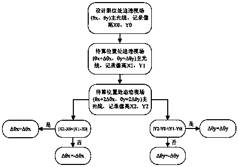
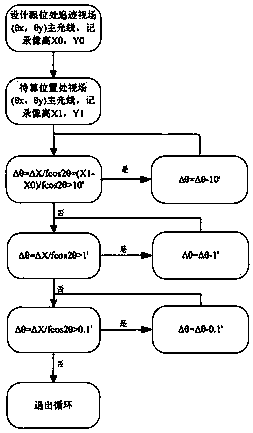
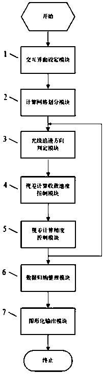
[0019] A numerical calculation method for visual optical system parallax. The steps of point-by-point parallax calculation are as follows: image 3 As shown, it includes an interactive interface setting module 1, a calculation grid division module 2, a ray tracing direction determination module 3, a parallax calculation convergence speed control module 4, a parallax calculation precision control module 5, a data induction analysis module 6, and a graphical output Module 7 and other seven parts.

[0020] The interactive interface setting module 1 includes option setti...


PUM


Abstract

The invention belongs to the technical field of optical display and relates to a visual optical system parallax calculation algorithm. The algorithm is mainly composed of an interactive interface setting module, a computational mesh module, a light trace direction judging module, a parallax calculation convergence speed control module, a parallax calculation precision control module, a data induction and analysis module, a graphical output module and so on, wherein the ray tracing direction judging module determines the ray tracing direction according to the trial and error method, then, according to the distance between the target point and the starting point, the convergence speed of the single calculation is determined by the parallax convergence speed control module. Through many iterative calculations, the tracking point gradually approaches to the target point, and finally the target point is determined by the parallax precision control module. As a visual optical system parallaxcalculation algorithm, that invention can realize one-key simulation analysis and graphic output of all field parallax in the entire pupil exit range of the visual optical system, has high parallax calculation efficiency and adjustable calculation precision, and provides an efficient and high-precision simulation analysis method for real-time calculation of the visual optical system parallax.

Description

technical field [0001] The invention belongs to the technical field of optical display and relates to a parallax calculation method. The present invention can be applied to virtual reality / augmented reality (VR / AR) systems such as head-up display / head-mounted display (HUD / HMD) that require imaging distance. Background technique [0002] When the aircraft is flying at high speed, the pilot needs to repeatedly look down at the airspeed, aircraft attitude and other information displayed on the lower display. In order to reduce the pilot's reaction time, military aircraft are equipped with a head-up display system (HUD), which can collimate and image relevant information in front of the eyes. Infinity, the pilot can see the information clearly without looking down while watching the distant target, which improves the battlefield generation rate. In order to see the infinite target and the relevant information displayed at the same time, both must be within the depth of field of ...

Claims


Application Information

Patent Timeline
Patent Type & Authority Applications(China)
IPC IPC(8): G06T7/00
CPCG06T7/97
Inventor 龙尤姬强李晓霞李卓高阳周亮耿云飞刘龙飞孙志勇付兴岭张海军
Owner LUOYANG INST OF ELECTRO OPTICAL EQUIP OF AVIC
Why Eureka
Try Eureka