Compressor stator, compressor and manufacturing method thereof

A manufacturing method and compressor technology, applied in the field of compressors and compressor stators, can solve problems such as low effective area of ​​stator slots, loss of stator slot area, and influence on motor performance, so as to achieve clearance reduction, optimized performance, The effect of increasing the motor slot full rate

Pending Publication Date: 2019-03-19
SHANGHAI HITACHI ELECTRICAL APPLIANCES CO LTD
View PDF0 Cites 2 Cited by
  • Summary
  • Abstract
  • Description
  • Claims
  • Application Information

AI Technical Summary

Problems solved by technology

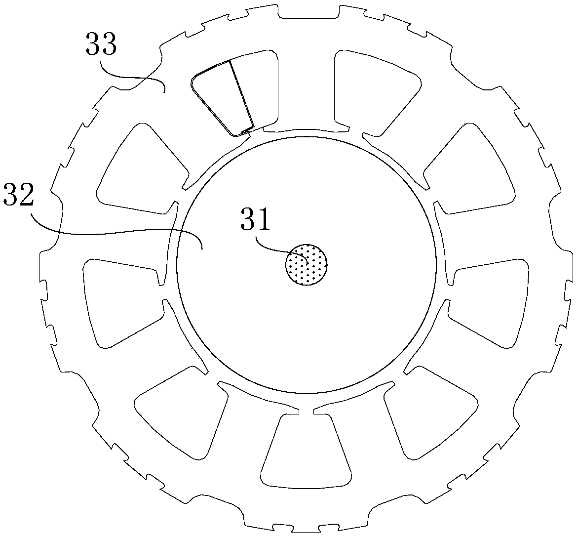
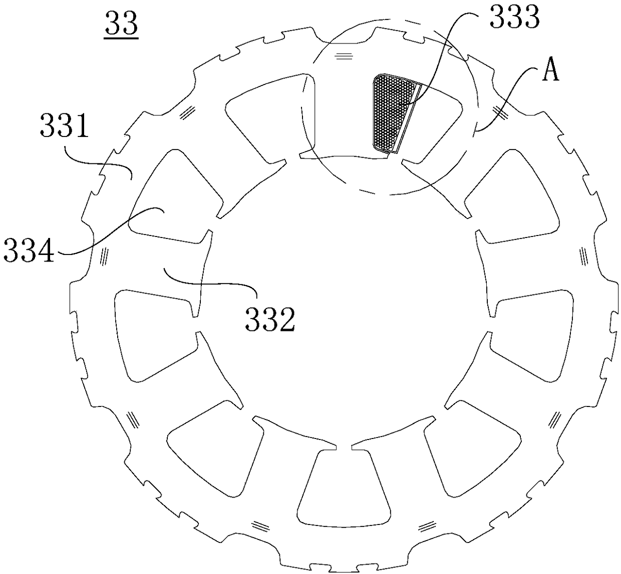
The stator 33 needs to stretch into the stator slot 334 for winding due to the winding needle (not shown) when winding, so that the winding needle occupies the area of ​​the part stator slot 334; 333) arrangement leads to gaps between the enameled wires, which further reduces the area of ​​the stator slot, making the effective area of ​​the stator slot lower and affecting the performance of the motor

Method used


Image

  • Compressor stator, compressor and manufacturing method thereof
  • Compressor stator, compressor and manufacturing method thereof
  • Compressor stator, compressor and manufacturing method thereof

Examples


Embodiment Construction

[0070] Example embodiments will now be described more fully with reference to the accompanying drawings. However, the example embodiments can be implemented in various forms, and should not be construed as being limited to the embodiments set forth herein. On the contrary, these embodiments are provided so that the present invention will be comprehensive and complete, and will fully convey the concept of example embodiments to those skilled in the art. The same reference numerals in the figures indicate the same or similar structures, and thus their repeated description will be omitted.

[0071] Figure 5 It is a schematic diagram of the compressor stator of the present invention. Image 6 It is a cross-sectional view of the T-like core of the compressor stator in the present invention. Figure 7 It is a cross-sectional view of the T-like core of the compressor stator of the present invention after winding. Figure 8 It is a schematic diagram of the combination of the T-like core...


PUM


Abstract

The invention provides a compressor stator, a compressor and a manufacturing method thereof. The compressor stator comprises multiple T-like iron cores which are mutually combined annularly; each T-like iron core is wound by a winding; each T-like iron core comprises a tooth part and a pair of connecting arms integrally extending from two sides of the first end of the tooth part respectively; thewinding corresponding to each T-like iron core performs winding along the tooth part of the T-like iron core; the winding passes through two included angle areas formed by two sides of the tooth partand the two connecting arms; the end part of the connecting arm is provided with at least one connecting tenon and / or at least one connecting slot; and two adjacent T-like iron cores are connected through the connecting tenons and / or the connecting slots. Through blocked individual winding, a winding pin can be prevented from occupying a stator slot, and in comparison with the traditional centralized winding motor, the motor slot filling rate Spf can be greatly improved, and optimization of the motor performance is further achieved.

Description

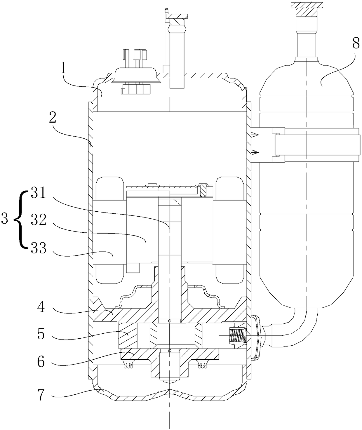
Technical field [0001] The invention relates to the field of refrigeration equipment, in particular to a compressor stator, a compressor and a manufacturing method thereof. Background technique [0002] At present, the permanent magnet synchronous concentrated winding motor used in the DC inverter compressor has an integral structure of the stator punch and adopts round enameled wire winding. [0003] Such as Figure 1 to 4 Shown. A compressor in the prior art includes: an upper cover 1, a housing 2, a motor 3, an upper cylinder head 4, a cylinder 5, a lower cylinder head 6, a lower cover 7, and an accumulator 8. Among them, the motor 3 and the cylinder 5 are housed in the housing 2. The motor 3 includes a rotor 32 and a stator 33; the crankshaft 31 transmits the rotational force of the motor 3 to the piston in the cylinder 5 to compress the refrigerant; the upper cylinder head 4 and The lower cylinder head 6 and the cylinder 5 jointly define the compression space and support the ...

Claims


Application Information

Patent Timeline
Patent Type & Authority Applications(China)
IPC IPC(8): H02K1/16H02K3/12H02K15/02H02K15/085
CPCH02K1/16H02K3/12H02K15/02H02K15/085H02K2213/03
Inventor 张志华张兴志范杰
Owner SHANGHAI HITACHI ELECTRICAL APPLIANCES CO LTD
Why Eureka
Try Eureka