Broadband piezoelectric vibration energy collection system

A piezoelectric vibration and energy harvesting technology, applied in the field of circuits, can solve problems such as frequency instability, failure of electronic equipment, and power attenuation

Active Publication Date: 2019-03-19
BINZHOU UNIV
View PDF4 Cites 16 Cited by
  • Summary
  • Abstract
  • Description
  • Claims
  • Application Information

AI Technical Summary

Problems solved by technology

[0002] Piezoelectric vibration energy harvesting technology is based on the positive piezoelectric effect of piezoelectric materials to convert vibration energy into electrical energy. When subjected to an external force in a fixed direction, the piezoelectric material deforms and generates electrical polarization inside. When the external force is removed, the piezoelectric material regenerates. Return to normal, so the mechanical energy is

Method used


Image

  • Broadband piezoelectric vibration energy collection system
  • Broadband piezoelectric vibration energy collection system

Examples


Embodiment 1

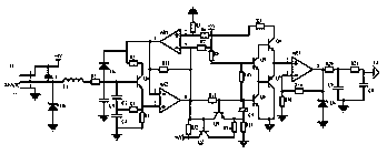
[0013] Embodiment 1, a broadband piezoelectric vibration energy harvesting system, including a frequency acquisition circuit, a voltage stabilizing push-pull circuit and an operational amplifier filter circuit, the frequency acquisition circuit collects the frequency of the electric power signal collected by the broadband piezoelectric vibration energy harvesting system, The RC circuit composed of resistor R1 and capacitor C3 is used to filter and then input into the voltage-stabilizing push-pull circuit. The voltage-stabilizing push-pull circuit uses a frequency modulation circuit composed of transistor Q1, capacitor C2, and capacitor C4 to stabilize the signal frequency. At the same time, the operational amplifier AR1 and The op amp AR2 forms a feedback regulator circuit to stabilize the voltage, and uses the triode Q2 and triode Q3 to form a composite circuit to filter out abnormal signals, and finally uses the triode Q4~transistor Q7 to form a push-pull circuit to prevent si...

Embodiment 2

[0016] Embodiment 2, on the basis of Embodiment 1, the operational amplifier filter circuit uses the operational amplifier AR3 to amplify the signal in phase, amplifies the signal power, and compensates the conduction loss of the signal. After being filtered by the RC filter circuit composed of C9, the signal transmitter E1 sends it to the remote control terminal of the broadband piezoelectric vibration energy collection system to further improve the anti-interference performance of the signal. The non-inverting input terminal of the operational amplifier AR3 is connected to the emitter of the transistor Q4, The inverting input terminal of the operational amplifier AR3 is connected to the resistor R18, one end of the resistor R19, the other end of the resistor R18 is grounded, and the other end of the resistor R19 is connected to the output terminal of the operational amplifier AR3, one end of the resistor R20, and the negative pole of the regulator D6 , the positive pole of th...


PUM


Abstract

The invention discloses a broadband piezoelectric vibration energy collection system. The system comprises a frequency collection circuit, a voltage stabilizing push-pull circuit and an operational amplifier circuit. The frequency collection circuit collects the frequency of the electric power signal collected by a broadband piezoelectric vibration energy collection system, the voltage stabilizingpush-pull circuit uses a frequency modulation circuit composed of a triode Q1, a capacitor C2 and a capacitor C4 to stabilize the signal frequency, simultaneously uses an operational amplifier AR1 and an operational amplifier AR2 to form a feedback voltage stabilizing circuit for voltage stabilization, and finally uses a triode Q4 to a triode Q7 to form the push-pull circuit to prevent the signalfrom crossover distortion; and the operational amplifier circuit uses an operational amplifier AR3 to perform in-phase amplification of the signal and simultaneously filters the signal by employing aRC filtering circuit composed of a resistor R20, a resistor R21, a capacitor C8 and a capacitor C9 to send the signal to the remote control terminal of the broadband piezoelectric vibration energy collection system through an emitter E1 so as to collect the electric energy power signal frequency collected by the broadband piezoelectric vibration energy collection system in real time, perform automatic calibration of the signal and prevent the data signal from distortion.

Description

technical field [0001] The invention relates to the field of circuit technology, in particular to a broadband piezoelectric vibration energy collection system. Background technique [0002] Piezoelectric vibration energy harvesting technology is based on the positive piezoelectric effect of piezoelectric materials to convert vibration energy into electrical energy. When subjected to an external force in a fixed direction, the piezoelectric material deforms and generates electrical polarization inside. When the external force is removed, the piezoelectric material regenerates. Return to normal, so the mechanical energy is converted into electrical energy. However, at this time, the electrical energy is used by electronic equipment after passing through the transformer and voltage stabilizer. The safe use of electricity by equipment requires real-time monitoring of electric energy. At the same time, the monitoring signal cannot be disturbed by electric and strong magnetic fiel...

Claims


Application Information

Patent Timeline
IPC IPC(8): H02N2/18
CPCH02N2/181
Inventor 庞帅许明清孔德平
Owner BINZHOU UNIV
Why Eureka
Try Eureka