
Arc fault identification unit

A technology of fault arc and identification unit, which is applied in the direction of electrical components, circuit devices, emergency protection circuit devices, etc.

Active Publication Date: 2019-03-19
SIEMENS AG
View PDF10 Cites 3 Cited by
  • Summary
  • Abstract
  • Description
  • Claims
  • Application Information

AI Technical Summary

Problems solved by technology

[0029] This has the disadvantage that optical waveguides or optical detection systems must be laid in parallel to the electrical lines or busbars to identify possible arc faults

Method used


Image

  • Arc fault identification unit
  • Arc fault identification unit
  • Arc fault identification unit

Examples


Embodiment Construction

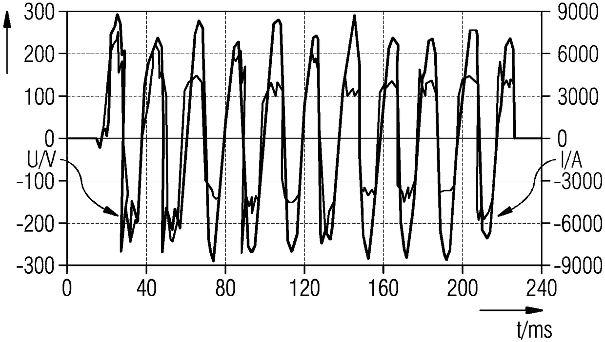
[0194] In circuits or grids where fault arcs burn, current and voltage curves with unique curves can be measured. exist figure 1 A general voltage and current curve for an arc fault is shown in . It shows a graphical representation of a voltage U and a current I over time after ignition of an arc or fault arc, in particular a parallel fault arc, in an electrical circuit, in particular a low-voltage circuit.

[0195] Time t is shown in milliseconds (ms) on the horizontal X-axis. On the vertical Y axis, the magnitude of the voltage U is depicted in volts (V) on the left scale. The magnitude of the current I is depicted in amperes (A) on the right scale.

[0196] After ignition of the arc, the curve of the current I is approximately sinusoidal. The curve of voltage U is severely distorted, for example "sawtooth" with rapid voltage changes. Roughly explained, the voltage curve is rectangular to a first approximation, rather than the usual sinusoidal curve. Considered in the ...


PUM


Abstract

The invention relates to an arc fault identification unit for an electrical three-phase alternating current circuit with three phase conductors and a neutral conductor, having - voltage sensors whichare assigned to each phase conductor and are intended to periodically determine phase / neutral conductor voltage values and phase / phase voltage values, - current sensors which are assigned to each phase conductor and are intended to periodically determine phase conductor current variables which are used to determine the phase conductor current value and a value for the change in the electrical current over time per phase, - an evaluation unit which is connected to the voltage and current sensors and is configured in such a manner that: - a current root mean square is compared with a current threshold value in each case and an excess current signal is emitted if the threshold value is exceeded, - arc voltages are calculated from phase / neutral conductor voltage values, phase / phase voltage values, phase conductor current values, concatenated currents, values for the change in the electrical current over time and concatenated change current values and are compared with threshold values, with the result that arc fault identification signals are output, - that further arc voltages are calculated from the phase / neutral conductor voltage values and phase / phase voltage values and are compared with further threshold values, with the result that further arc fault identification signals are output, - that an arc fault identification signal on the output side is output if at least one excesscurrent signal and one arc fault identification signal are present.

Description

technical field [0001] The invention relates to an arc fault detection unit, a circuit breaker, a short circuit and a method for detecting an arc fault. [0002] This patent application claims priority from the following applications: [0003] PCT / EP2016 / 062274 [0004] PCT / EP2016 / 062273 [0005] PCT / EP2016 / 062272 [0006] PCT / EP2016 / 062271 [0007] (European Patent Office) [0008] as well as: [0009] 102016209444.0 [0010] 102016209443.2 [0011] 102016209445.9 [0012] (German Patent Office). [0013] The contents of the above seven applications are hereby incorporated by reference into this application. Background technique [0014] In low-voltage circuits or installations or low-voltage networks, ie circuits with voltages up to 1000 V AC or 1500 V DC, short circuits are often associated with fault arcs occurring, for example parallel or series fault arcs. Low voltage means in particular a voltage greater than a small voltage with values ​​of 25 volts or 50 ...

Claims


Application Information

Patent Timeline
IPC IPC(8): H02H1/00H02H3/44H02H3/38H02H3/50
CPCH02H3/38H02H1/0015H02H3/05H02H9/041
Inventor J.迈耶P.谢格纳K.温兹拉夫S.威德曼
Owner SIEMENS AG
Learn More