
Femoral posterior condyle osteophyte removing device

A technology of osteophyte and femur, applied in the field of osteophyte removal device of the posterior femoral condyle, can solve the problems of patient injury, joint instability, misjudgment of the state of straightening balance, etc., and achieve the effect of improving accuracy, reducing pain, and ensuring the effect

Pending Publication Date: 2019-03-22
XIANGYA HOSPITAL CENT SOUTH UNIV
View PDF0 Cites 4 Cited by
  • Summary
  • Abstract
  • Description
  • Claims
  • Application Information

AI Technical Summary

Problems solved by technology

The problem with the current technology is that the osteophyte at the position of the posterior femoral condyle will have a great impact on the judgment of the balance of the straightening gap
Due to the particularity of the position of the posterior condyle osteophytes, conventional surgical techniques and instruments must completely resect the posterior femoral condyle to reveal and remove the posterior condyle osteophytes. In this way, the presence of posterior femoral condyle osteophytes in patients will cause the surgeon to misjudge In the state of straightening balance, choose to loosen (that is, partially cut) the ligaments on both sides of the knee joint to achieve the balance of the straightening gap, which will cause additional damage to the patient, which will lead to joint instability after replacement, affecting the effect of surgery and the function of the patient's knee joint state

Method used


Image

  • Femoral posterior condyle osteophyte removing device
  • Femoral posterior condyle osteophyte removing device
  • Femoral posterior condyle osteophyte removing device

Examples


Embodiment Construction

[0021] In order to better understand the present invention, the invention will be described in further detail below in conjunction with the accompanying drawings and implementation examples, but the embodiments of the present invention are not limited thereto, and the scope of protection of the present invention also relates to those skilled in the art who can achieve according to the concept of the present invention. Think of the equivalent technical means.

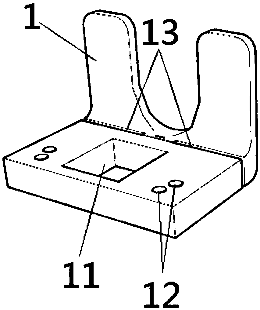
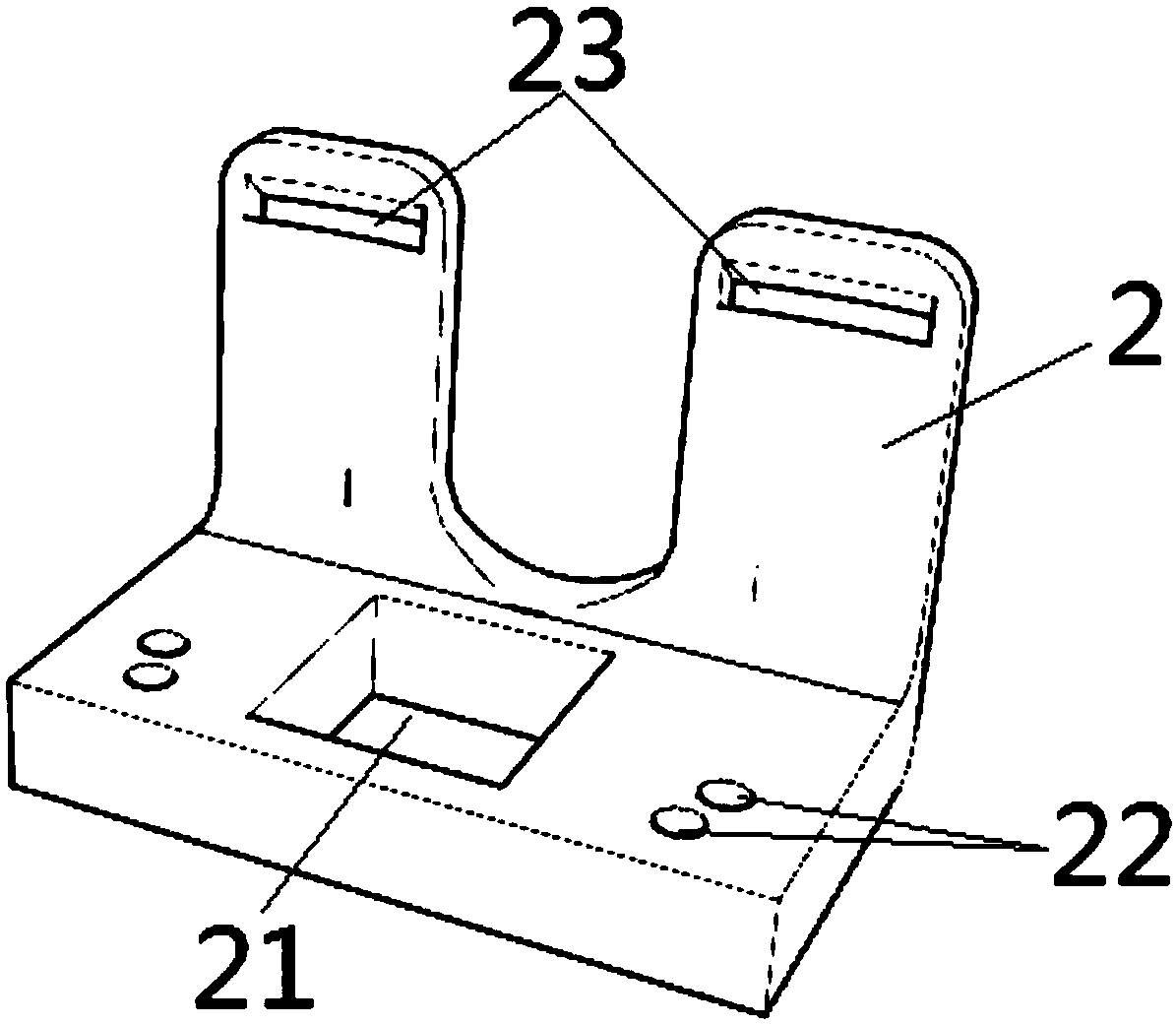
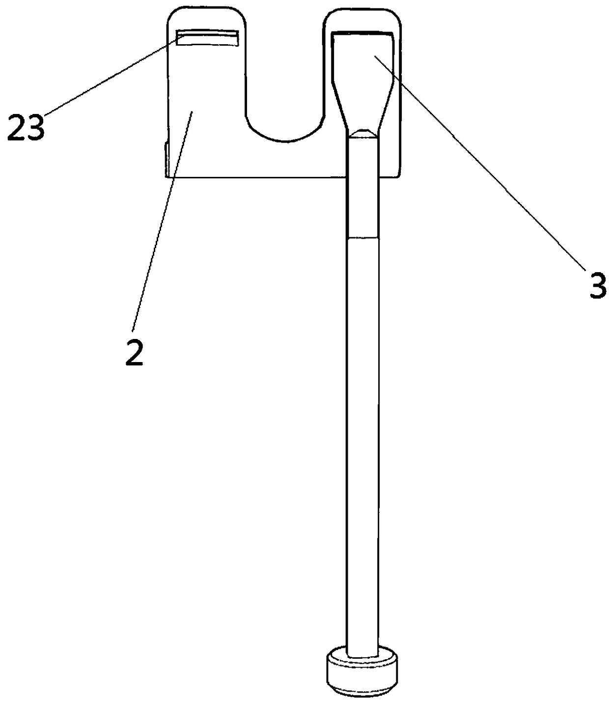
[0022] Such as Figures 1 to 6 Shown, a kind of osteophyte removal device of posterior condyle of femur comprises posterior condyle osteotomy plate 1, posterior condyle osteophyte removal guide plate 2 and posterior condyle osteophyte removal arc osteotome 3, and described posterior condyle osteotomy plate 1 is L Type, described posterior condyle osteotomy plate 1 comprises posterior condyle fixation plate and posterior condyle limiting plate perpendicular to each other, and the middle part of described posterior condyle...


PUM


Abstract

A femoral posterior condyle osteophyte removing device comprises a posterior condyle osteotomy plate, a posterior condyle osteophyte removing guide plate and a posterior condyle osteophyte removing arc-shaped osteotome. The posterior condyle osteotomy plate comprises a posterior condyle fixing plate and a posterior condyle limiting plate which are perpendicular to each other, a through hole for observing fitting condition of the posterior condyle fixing plate with femur is formed in the middle of the posterior condyle fixing plate to serve as a first observation window, the posterior condyle fixing plate is provided with multiple first nail holes convenient for fixing the posterior condyle fixing plate onto the femur on two sides of the first observation window, two osteotomy sawblade guide grooves parallel to the posterior condyle limiting plate are formed in a position, close to the posterior condyle limiting plate, of the posterior condyle fixing plate and arranged on two sides of the femur symmetrically by taking the femur as a center, a gap is reserved between the osteotomy sawblade guide grooves, and each osteotomy sawblade guide groove is a through groove. By the device, interference of posterior condyle osteophyte on straightening gap judgment is avoided, balance of straightening position in knee joint replacement is ensured, balance accuracy is improved, suffering of apatient is relieved, and effect of knee joint replacement surgery is ensured.

Description

technical field [0001] The invention relates to a device for removing osteophytes of the posterior femoral condyle. Background technique [0002] Patients with severe knee joint disease often need to consider artificial knee replacement surgery in the late stage to restore knee joint function. In knee replacement surgery, it is necessary to judge the gap balance. The gap balance technique is a method for positioning the femoral external rotation osteotomy, while the traditional knee replacement surgery process is to perform osteotomy on the anterior femoral condyle to obtain equal medial and lateral dimensions. After the joint space, judge the gap balance in the straight position, and then perform posterior condylar osteotomy, and then remove the possible posterior condylar osteophytes, and finally install the artificial knee joint. The problem with the current technology is that the osteophyte at the posterior femoral condyle will greatly affect the judgment of the balance...

Claims


Application Information

Patent Timeline
Patent Type & Authority Applications(China)
IPC IPC(8): A61B17/16A61B17/17
CPCA61B17/1657A61B17/1659A61B17/1675A61B17/1732A61B17/1764
Inventor 谢杰刘东昊胡懿郃曾敏李辉
Owner XIANGYA HOSPITAL CENT SOUTH UNIV
Learn More