Small efficient sand screening machine for civil engineering

A technology of civil engineering and sand screening machine, which is applied in the direction of screening, solid separation, grille, etc., can solve the problems of high labor intensity, low sand screening efficiency, and poor sand screening effect, so as to improve the effect and efficiency of sand screening , Prolong the residence time and reduce the production cost

Inactive Publication Date: 2019-03-22
曹林同
View PDF0 Cites 7 Cited by
  • Summary
  • Abstract
  • Description
  • Claims
  • Application Information

AI Technical Summary

Problems solved by technology

[0003] Yellow sand is one of the more commonly used materials in civil engineering construction. In order to meet the requirements for the use of yellow sand, many purchased yellow sands need to be screened in the later stage. At present, most construction sites still use manual sand screening. , the labor intensity of workers is high, the efficiency of sand screening is low, and the effect of sand screening is poor

Method used


Image

  • Small efficient sand screening machine for civil engineering
  • Small efficient sand screening machine for civil engineering
  • Small efficient sand screening machine for civil engineering

Examples


Embodiment 1

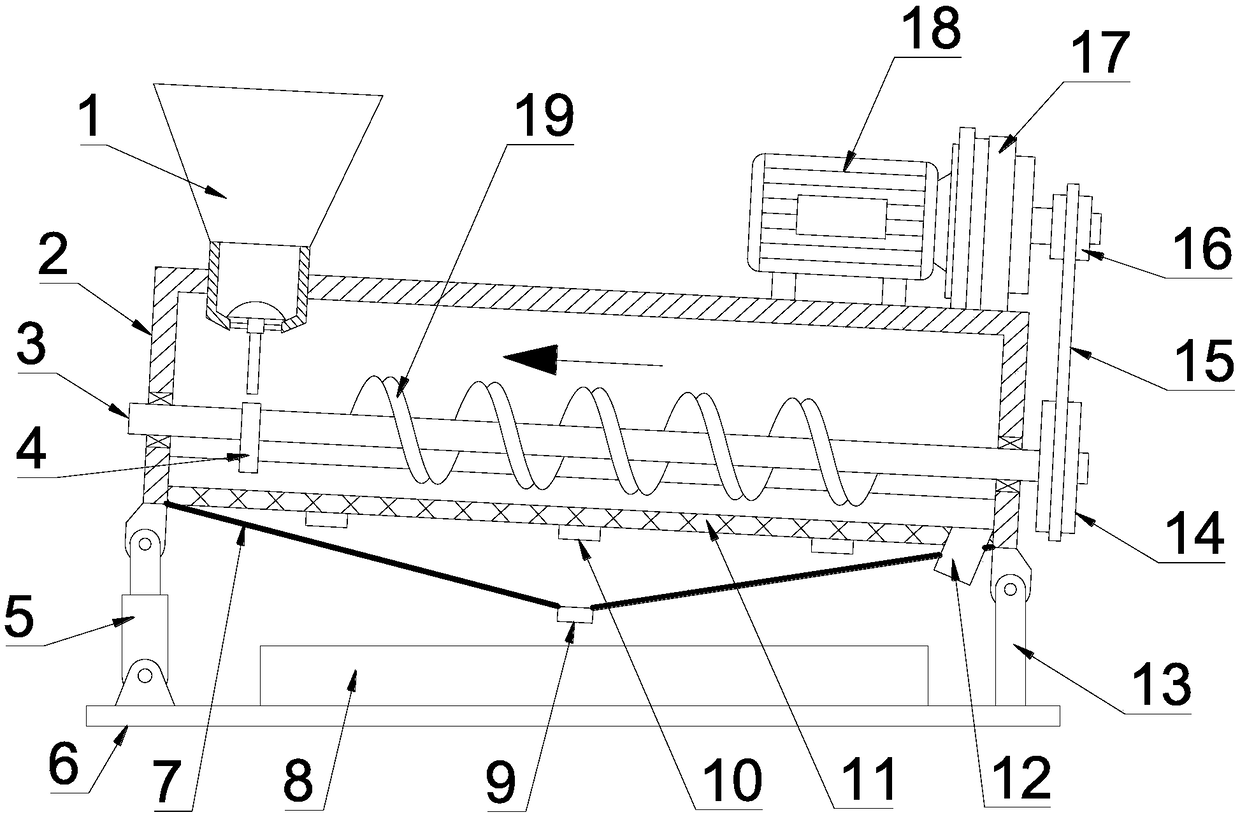
[0027] see Figure 1~4 , in an embodiment of the present invention, a small-scale high-efficiency sand screening machine for civil engineering includes a box body 2, the box body 2 is a lower opening structure, and the bottom of the box body 2 is equipped with a sand screen mesh plate 11, a sand screen net The plate 11 is a downward arc-shaped concave structure in the middle, and a plurality of vibrators 10 are arranged on the lower side of the sand screen plate 11, and the vibrator 10 drives the sand screen plate 11 to vibrate, which is beneficial to sieve out the sand material. The bottom of the body 2 is also provided with a hopper 7, the middle part of the hopper 7 is provided with a discharge pipe 9, the hopper 7 is used to guide the sand material, and the discharge pipe 9 is used to discharge the sand material. The right end of the bottom of the body 2 is provided with a slag discharge pipe 12 for discharging impurities on the upper right side of the sand screen plate 11...

Embodiment 2

[0030] see Figure 1~3 , the difference between this embodiment and embodiment 1 is:

[0031] In this embodiment, a base 6 is provided below the box body 2, and a receiving groove 8 for holding the sand discharged from the discharge pipe 9 is arranged on the base 6, and the left and right ends of the bottom of the box body 2 are provided with There are telescopic device 5 and strut 13, the upper ends of said telescopic device 5 and strut 13 are hingedly connected with box body 2, the lower end of telescopic device 5 is hingedly connected with base 6, and the lower end of strut 13 is fixedly arranged on base 6, through telescopic The angle of the box body 2 can be adjusted when the device 5 works.

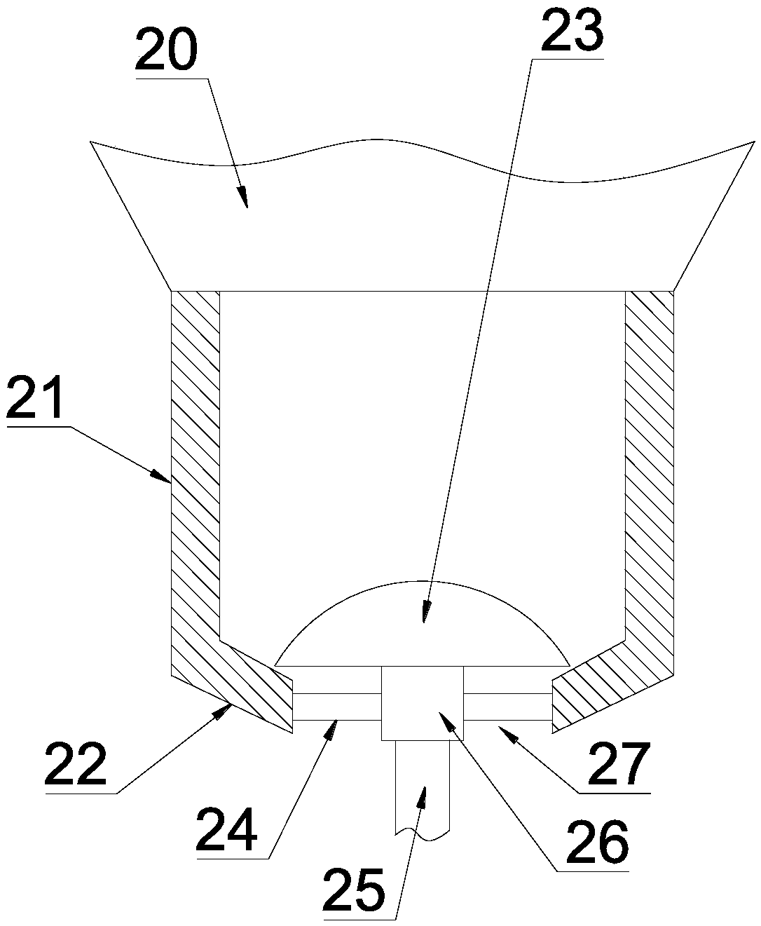
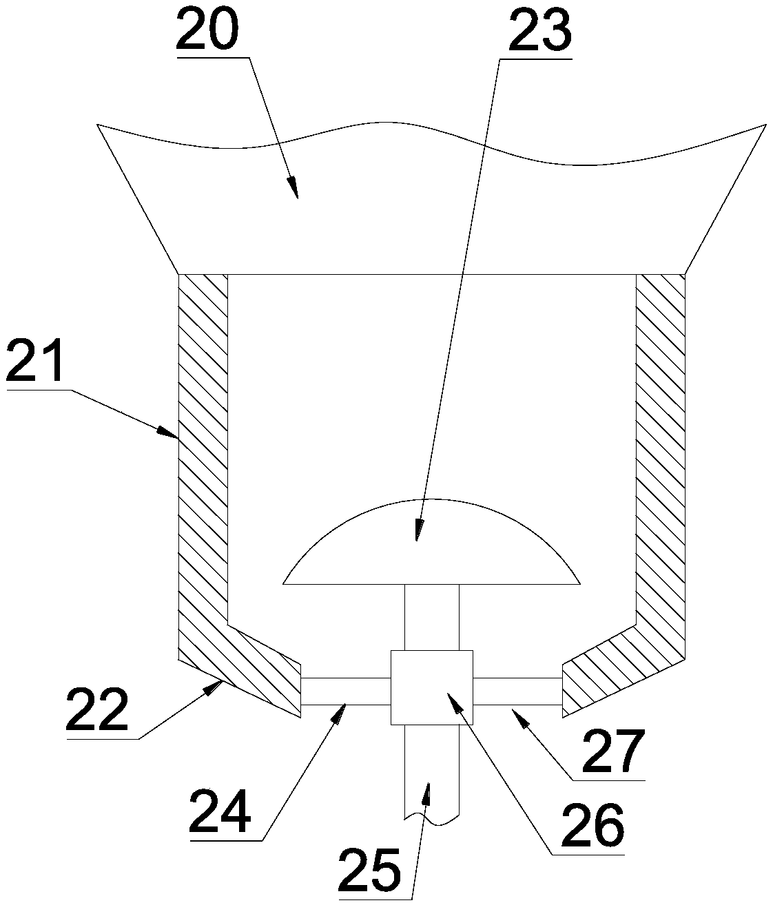
[0032] In this embodiment, a feeding mechanism 1 is provided on the left side of the top of the box body 2, and the feeding mechanism 1 includes a feeding pipe 21. The lower end of the feeding pipe 21 extends to the inner side of the box body 2, and feeds The feed pipe 21 is verti...


PUM


Abstract

The invention discloses a small efficient sand screening machine for civil engineering. The machine comprises a box body; a sand screening net plate is matched at the bottom of the box body; multiplevibrators are arranged on the lower side of the sand screening net plate; a rotating shaft is arranged in middle of the upper side of the sand screening net plate; spiral blades matched with the bottom of the sand screening net plate are mounted on the rotating shaft; a driven belt wheel is fixedly mounted on the rotating shaft on the right side of the box body; the driven belt wheel is connectedwith a driving belt wheel mounted on an output shaft of a speed reducer through a triangular belt; an input shaft of the speed reducer is connected with an output shaft of a driving motor; and the speed reducer and the driving motor are fixed at the top of the box body. The machine can use one motor for controlling unloading and overturning of sand and prolonging the stop time of the sand, and canadjust the angle to improve the sand screening effect and efficiency and to reduce the production cost.

Description

technical field [0001] The invention relates to the field of civil engineering equipment, in particular to a small high-efficiency sand screener for civil engineering. Background technique [0002] Civil engineering is a general term for the science and technology of building various land engineering facilities. It not only refers to the applied materials, equipment and technical activities such as survey, design, construction, maintenance and repair, but also refers to the object of engineering construction. That is, various engineering facilities built on the ground or underground, on land, directly or indirectly serving human life, production, military affairs, and scientific research, such as houses, roads, railways, pipelines, tunnels, bridges, canals, dams, ports, power stations, Airports, offshore platforms, water supply and drainage, and protection projects, etc. Civil engineering refers to various technical work such as survey, planning, design, construction, inst...

Claims


Application Information

Patent Timeline
Patent Type & Authority Applications(China)
IPC IPC(8): B07B1/28B07B1/46
CPCB07B1/28B07B1/46
Inventor 曹林同史蕊
Owner 曹林同
Why Eureka
Try Eureka